My cousin recently got ahold of me, saying that he was having trouble with his Brother FAX-2840 fax machine/laser printer. It still worked fine as a fax machine or copy machine, but he couldn’t print to it from his Windows 10 computer. He has a business where he needs to be able to print forms and receipts for customers, so it’s a big deal when he can’t print. This particular printer only has a USB port for PC connectivity. It’s connected directly to his computer. I went through all the basic troubleshooting with him:

“Did you try unplugging and replugging it? Did you try a different USB port on the computer? Maybe the computer needs a reboot?” None of that fixed it. I stopped by after work to take a look, hoping that it was just some simple glitch that I could resolve.

When I arrived, it quickly became apparent that this was more than a glitch. Whenever I plugged the printer into his computer, a message popped up saying: The last USB device you connected to this computer malfunctioned, and Windows does not recognize it.

Read the rest of this entry

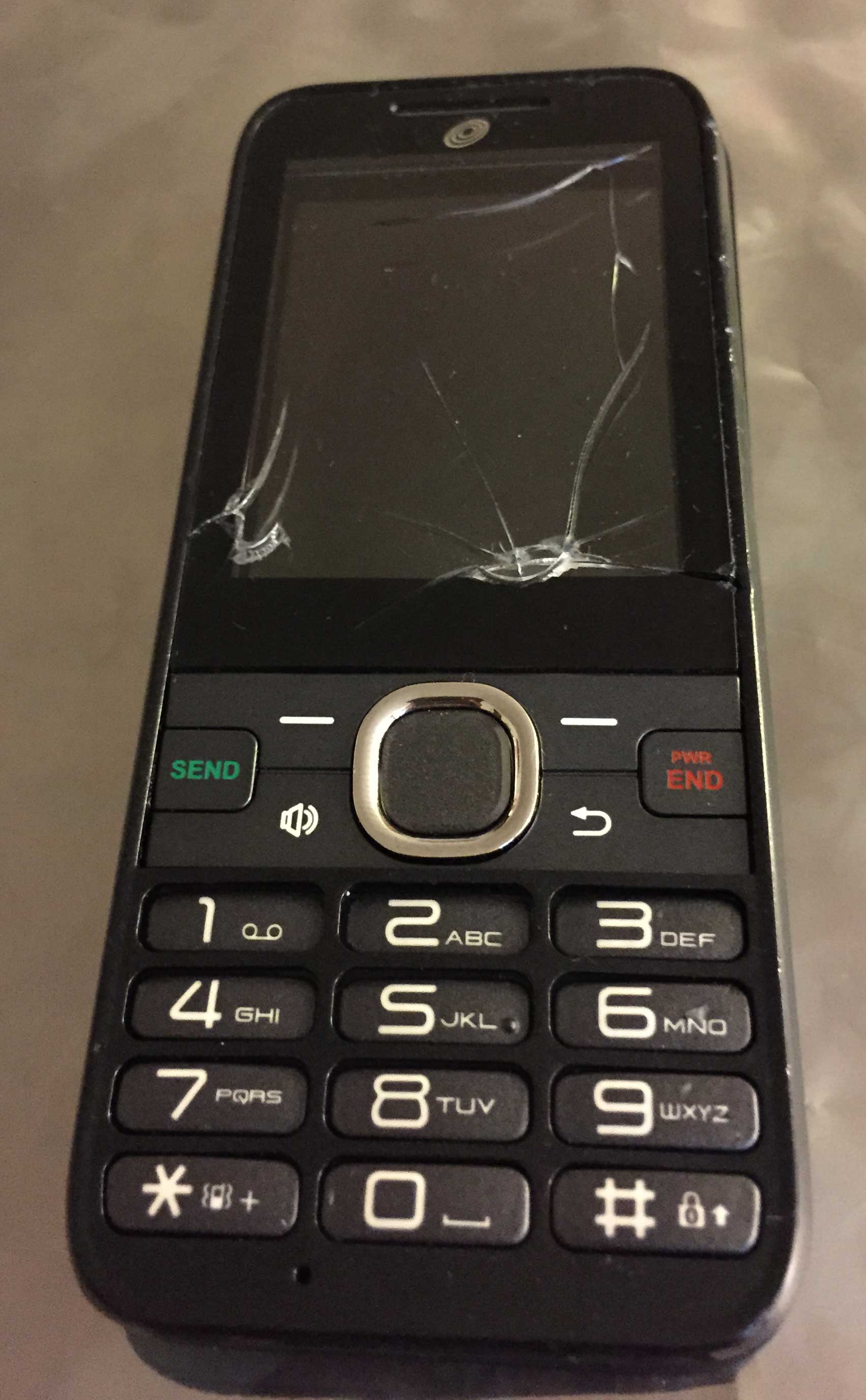
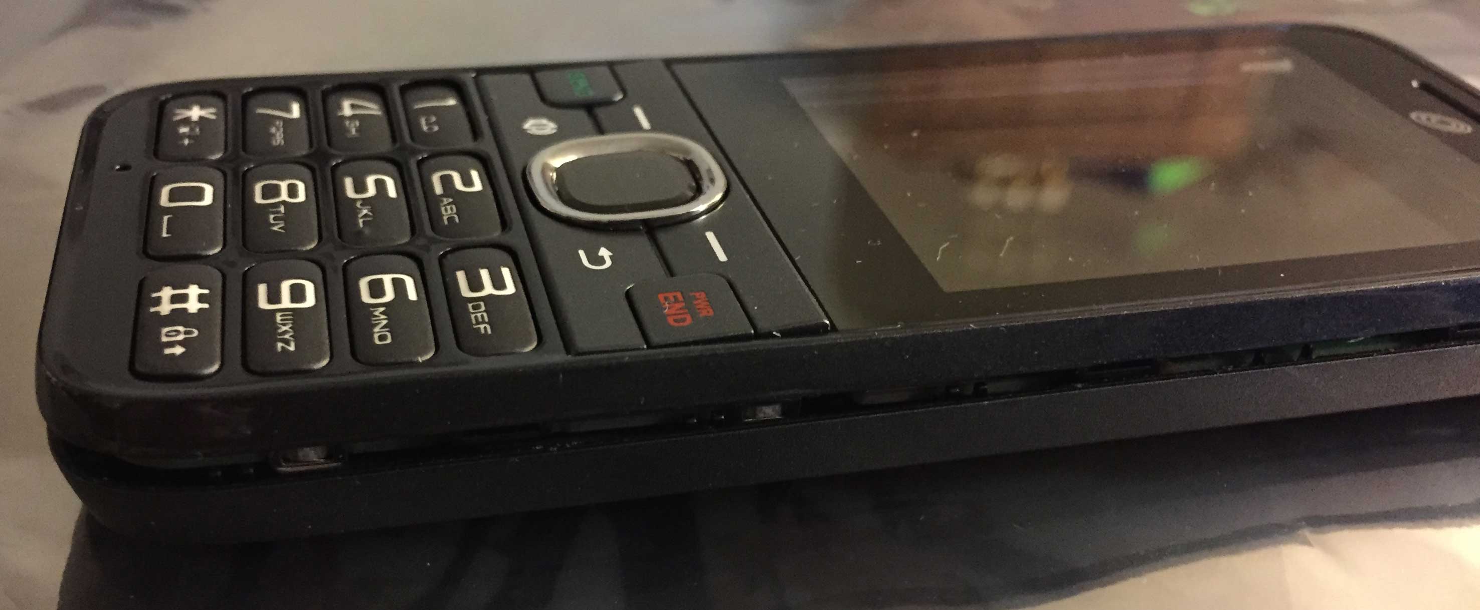
Recently, my dad’s TracFone Huawei H110C cell phone (with over 900 minutes and 200 service days) was a victim of mistaken identity. It was loaned out to someone else, and their dog thought it was a chew toy.

BrokenFront

I was called to the rescue. The phone still worked, but the display was all screwed up so I couldn’t see anything. My first thought was to transfer the service (phone number, minutes, service days) to a new phone, but I discovered that you need to enter and read back codes on the old phone in order to transfer your service, which you obviously can’t do with a broken display. I also read on forums that it can be time-consuming to work with TracFone to recover your minutes from a broken/lost/stolen phone, so I didn’t really want to mess around with that.

I tore apart the old phone to try to see if it was possible to replace the display. I was able to remove the LCD display module, but I couldn’t find that particular display available for purchase anywhere online. It may have been custom-made for Huawei. A brand new H110C costs less than $10 at Wal-Mart, so I decided the easiest approach would be to buy a new H110C and remove its display, then plug the new display into the old, broken phone and hope that it would work long enough to get the minutes transferred off of it.

It worked! I was able to enter the codes needed to transfer the service to another new H110C, which I also bought at Wal-Mart. Rather than reassemble the first new phone and transfer the service to it, I decided it would make more sense to buy a second new phone because some components in the phone are glued together, and you have to sort of mangle a metal shield in the phone in order to get to the display. So this process required me to buy two new H110Cs at Wal-Mart for a total price of $19.76. Not bad! Other than setting off the alarm at Wal-Mart when I left because the employee who helped me forgot to do something to the phone boxes, buying the phones was a painless process.

I hope I can help someone else out who runs into this problem, so here’s a tutorial on removing/replacing the display in a Huawei H110C.

Get the phone out of the box

Remove the phone from the box. Leave the battery out (or if it’s already installed, remove it).

NewPhone1


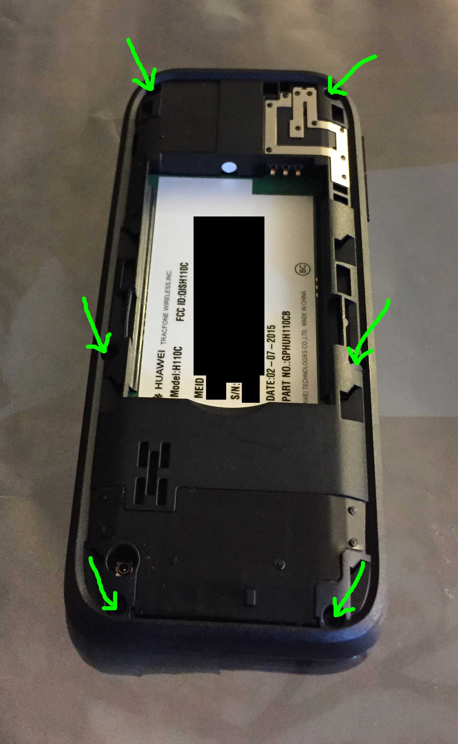
Remove the six screws from the back

There are six screws on the back of the phone. Remove them. They are Torx T5 screws, so you will need an appropriate screwdriver. One of them (right center in the picture) is covered with a white sticker as proof that you haven’t opened it. We’re going to void our warranty here anyway, so no big deal.

Screws


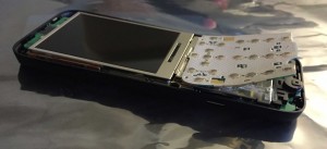
Separate the two halves

Removing the screws will not automatically separate the plastic pieces that hold the phone together. Carefully slide an old credit card or similar tool in between the two halves to release the latches that hold it all together. Work your way around the entire phone until the two halves are separated, and then lift the top of the case away.

Split

Halves


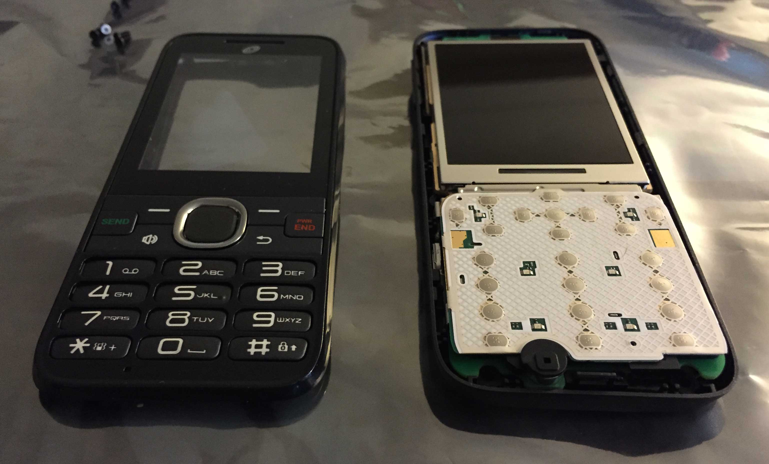
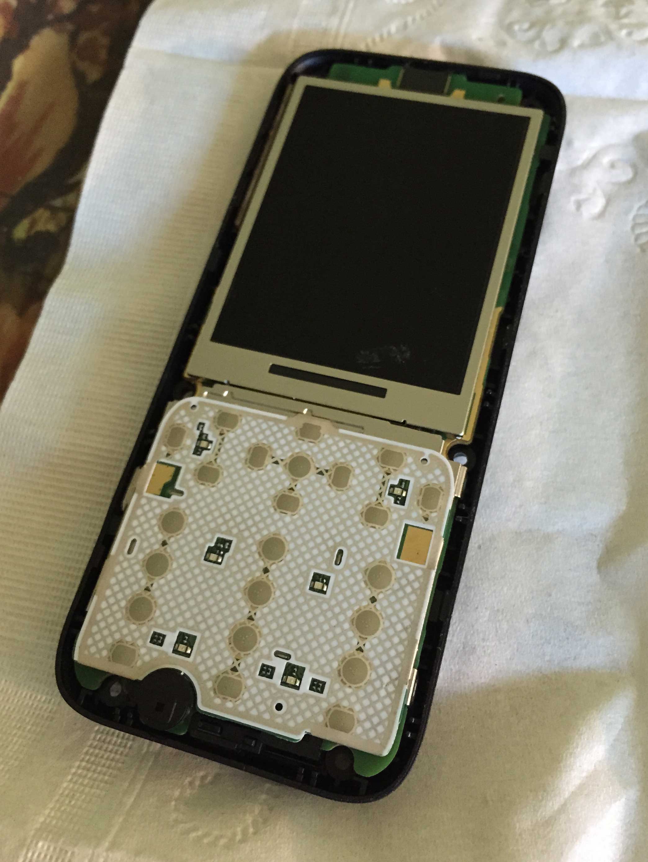
Remove the button board

The buttons are on a small flexible white circuit board. It is glued (and/or taped?) to the metal shield underneath it. Carefully peel it up off the shield. There is a connector on the bottom of it that connects to the main phone circuit board below. The connector should easily disconnect as you peel the button board away. It’s difficult to not bend the board, but try to keep it as straight as possible because we will need to use it again when we turn on the old phone.

Peel

KeysRemoved

KeyBoard


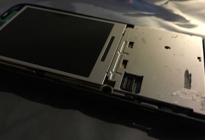
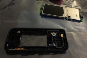
Pull the bottom half of the phone out of the plastic case

At this point you should remove the main phone board and display from the bottom case. If you push it around enough it should come out. I struggled with it a little bit, but eventually I was able to snap the circuit board out.

RemovedFromCase


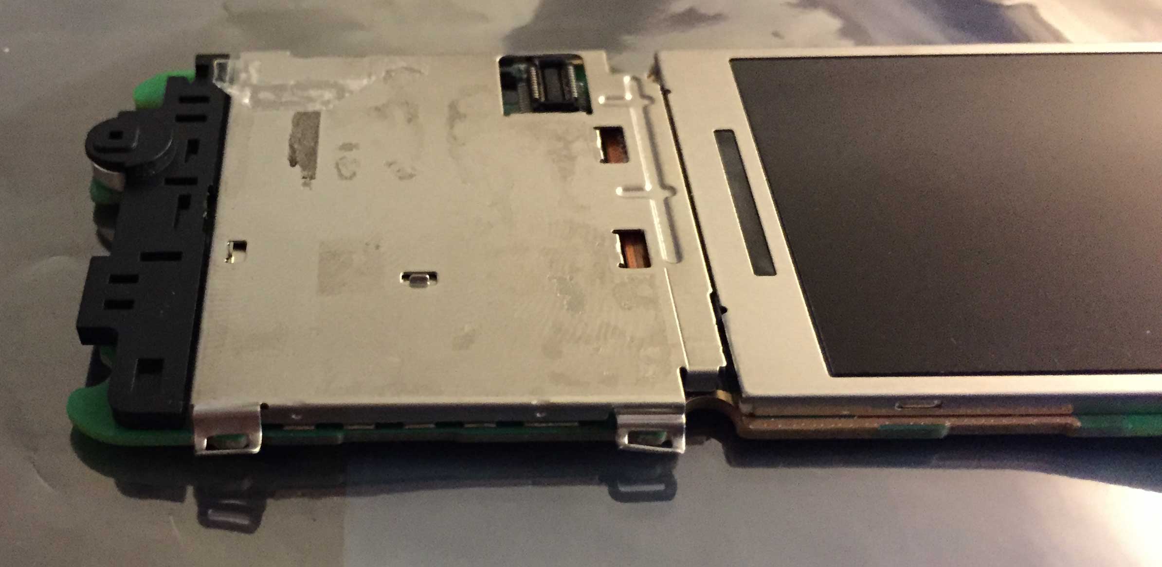
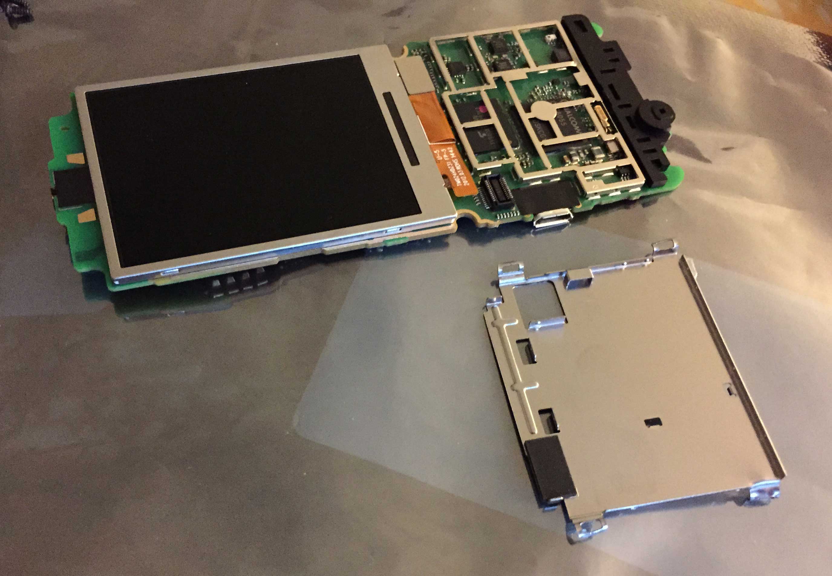
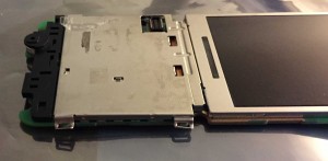
Remove the metal shield

In order to get to the connector that connects the display to the board, you will need to remove the metal shield. This shield is probably an EMI/RF shield blocking interference to/from the phone. There are four tabs that hold it in place–two on each side. Peel them back, and then pop the metal shield off. This may take some force, so be careful. I used a small set of needle-nose pliers. On the first phone I opened (the broken one), I mangled the shield pretty badly. I did a better job on the second one, but I wouldn’t count on necessarily putting it back together when you’re done unless you’re really desperate to only buy one new phone instead of two.

PeelBackClips

MetalCoverRemoved


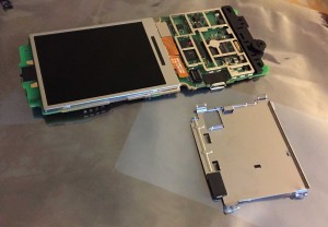
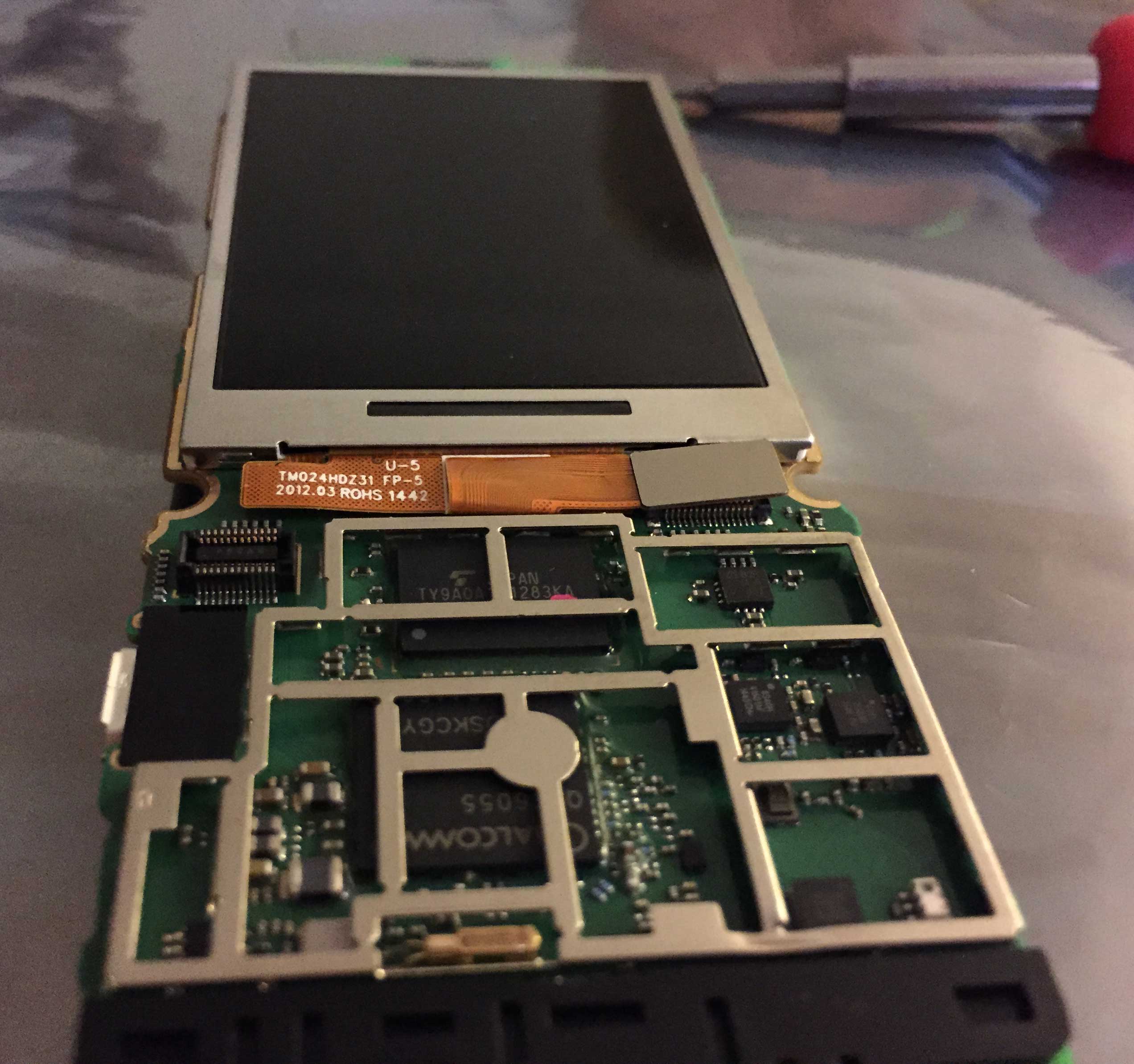
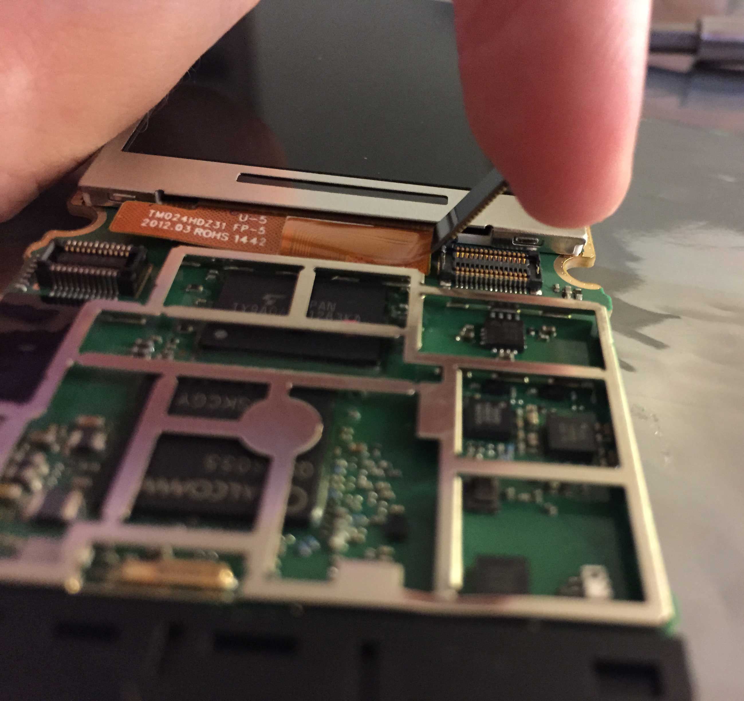
Disconnect the display from the main board

The display is connected to the main board through a small gray connector attached to a ribbon cable. It is easy to remove. Gently pry it up (I used a small screwdriver).
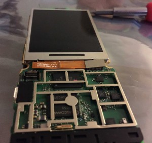
DisconnectDisplay1

DisconnectDisplay2


Remove the display

Removing the display is pretty difficult because it is also glued/taped down. I couldn’t figure out exactly what they used, but it seemed to be some sort of really sticky tape. I carefully stuck a thin screwdriver between the phone board and the display, and very carefully pried it up a little bit at a time to break the bonding. Eventually it lifted off the board. Be very careful here, especially with the brand new phone, because you don’t want to damage the new display.

DisplayRemoved


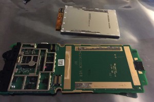
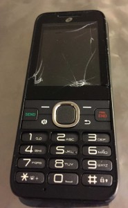
Repeat this process on your broken phone

Do the same thing to remove the broken display from the old phone. As you can see, the old one was damaged by a dog bite.

BrokenDisplay


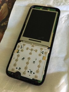
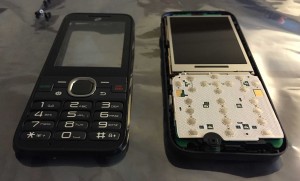
Put the new display into the old phone

Basically, just do these steps in reverse. Plug the new display and one of the button boards into the old phone’s main board. I left the metal shield off because I knew I would only have the old phone turned on for a few minutes. I also covered the bottom of the button board with Kapton tape to ensure it would stay insulated from any metal underneath, although I don’t know how important that was.


Write down everything about the old phone

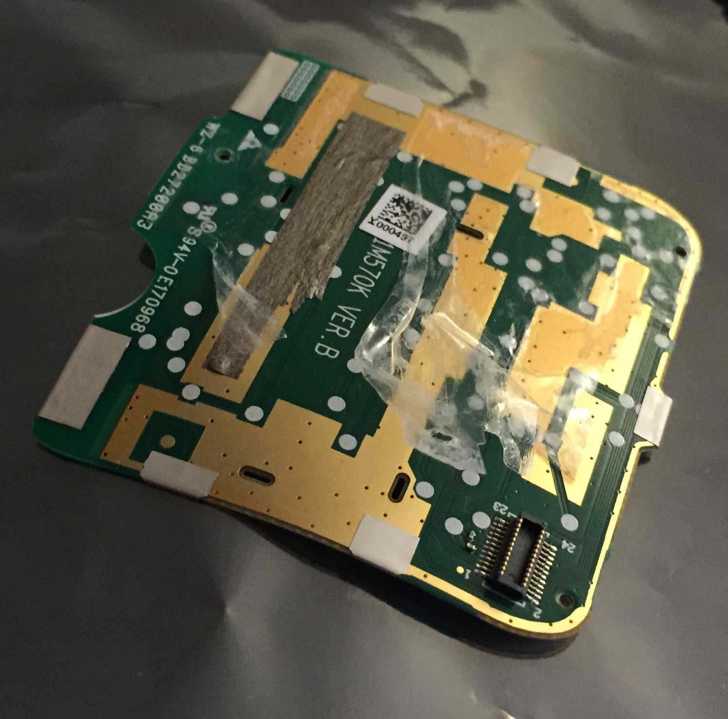
You will need the MEID of the old phone during the transfer process. TracFone will probably already have your old phone’s MEID on file, but just in case, write it down or take a picture of it (it’s inside the battery compartment, on the back of the main circuit board).


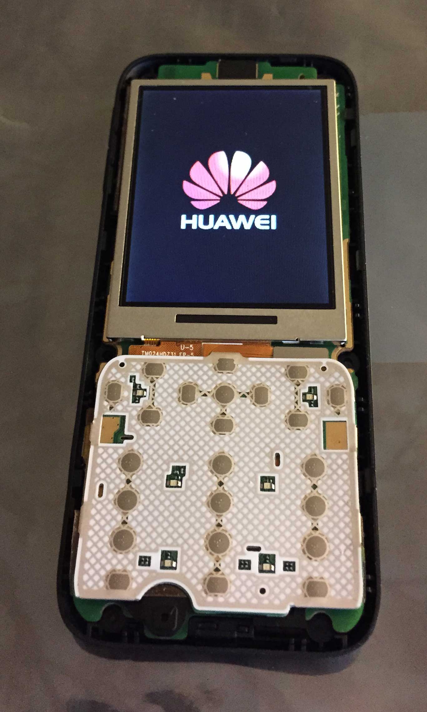
Turn on the old phone

Put the old phone (with new display and button board) into a case, insert a battery, and turn it on. You can press the little buttons on the button board that correspond with the phone’s keys. Cross your fingers! Here’s what I saw after a second:

Success


Begin the transfer process

Now, go to TracFone’s website and start the process of transferring the old phone’s service to the second new (unopened) phone. The TracFone site will walk you through entering some codes on the old phone and typing the result codes into their webpage to determine the number of remaining minutes and service days.

While you have the old phone turned on, be sure to write down the old contacts and settings so you can put them into the new phone.


All done!

After that, I was instructed to dial a number on the new phone to activate it. Activation worked painlessly and the new phone worked great. At that point I was able to turn off the old phone and get rid of it. Remember, lithium-ion batteries are dangerous if they get damaged, so don’t put them in the garbage–take them somewhere that can dispose of them properly. In all honesty, the dog was probably lucky that he didn’t puncture the battery.

The tape/glue/whatever was pretty annoying, and the metal shield was a pain to remove, but other than that, this phone wasn’t very difficult to take apart. It was definitely worth the less-than-$20 price to buy a brand new phone and another new LCD donor phone in order to recover all those minutes and service days from the old phone. I hope this little tutorial helps someone out there!


I was so excited about fixing that Polaroid DVD recorder on Thursday (see my last post) that I remembered I had an RCA DVD recorder also sitting around that had quit working. Quite a while ago, we had a power outage. When the power came back on, my RCA DRC8052NB DVD recorder wouldn’t turn on. The LCD on the front panel turned on, and the message “HELLO” scrolled across it. I couldn’t get it to stop without unplugging the power.

The normal behavior when you first plug it in is for the “HELLO” message to scroll across for a few seconds. Then it’ll say something like “NO DISC”. Finally, it’ll shut itself back down and display the time, waiting for you to power it back up. Then, when you press the power button to turn it on, the “HELLO” message will come back for a few seconds, and finally it will turn on and display the current channel number or “NO DISC” or whatever else, depending on the mode you left it in when it was last turned off.

Anyway, so “HELLO” kept scrolling indefinitely. I figured it was a similar problem to what I saw on the Polaroid DVD recorder. The difference was that in the Polaroid DVD recorder, nothing displayed on the front panel. At first thought, I figured it might have something to do with the power board. But because the LCD was displaying a message, that made me a bit skeptical because you’d think a program on the main DVD board would be displaying that message, which would mean the main DVD board would be getting a good 3.3V power input.

I went ahead and checked it out with my multimeter. This power supply board is a bit different because it needs some sort of signal to tell it to turn on. I tried powering it up with its cable that goes to the “motherboard” (I don’t know the technical term for it, so I’ll call it the motherboard from now on) disconnected, but nothing happened. So I had to leave the motherboard plugged into the supply while measuring the output voltages. Anyway, the 3.3V output was only 2.8V, and several of the other voltages were pretty far out of range too. Some of the 5V outputs were only 4.5V, and the 40V output was only 35V. Sounds like a power supply problem again…I guess the “HELLO” message doesn’t necessarily mean the output from the power supply is good.

My suspicion was confirmed when I found some other postings online about this exact same model. In fact, this question on FixYa has several answers all pointing to a single capacitor that was probably causing the problem. Another post on FixYa also seemed to point toward capacitors.

None of the capacitors on the power supply board looked weird. In the Polaroid DVD recorder I fixed earlier, two of the capacitors were bulging. In this one, nothing looked weird to me. But an answer to that first FixYa question I linked to above also pointed out that the capacitor looked OK but was still bad.

Based on the first FixYa question, I went ahead and desoldered the 1000uF, 6.3V capacitor (C22). Multiple answers in that question implied that particular capacitor was the source of the problem. Interestingly enough, the footprint on the board for that capacitor is a lot larger than the actual capacitor soldered in. It makes me think that perhaps the board was originally designed for a cap with higher ratings.

Luckily, when I fixed the Polaroid DVD recorder, I ordered two of each capacitor I replaced, even though I only needed one. As you’ll remember, one of those capacitors was a 1000uF, 16V capacitor. It perfectly fit the footprint on the RCA DVD recorder’s power board. Since it was the same capacitance with a higher max voltage, I was good to go.

I soldered it in, put the power board back into place and reconnected all of the wires going into it. I plugged the DVD recorder back into AC power. The “HELLO” message came on, and I crossed my fingers. A couple of seconds later, the “NO DISC” message appeared, and shortly thereafter, the display read “12:00 AM”. Awesome!

I pressed the power button to turn the DVD recorder back on. Then I measured some of the power board’s outputs. The 3.3V output now was correctly at 3.3V. The 40V output was still pretty low (36V) but it was higher than it was. I didn’t bother to check the 5V outputs because it was a tight fit and I didn’t want to short anything like I did in the Polaroid one!

Anyway, thanks to roybro123 and neveo1999 on FixYa. Their answers helped revive my DRC8052 DVD recorder.

Before I realized that I already had a 1000uF capacitor sitting around here, I ordered all new capacitors on DigiKey for the DVD recorder. Oh well–it’ll be nice to have the spare parts laying around in case another one goes bad.

In conclusion, cheap capacitors suck. Companies are saving a few pennies by using cheap capacitors instead of high-quality ones. Or maybe they’re not allowing for proper ventilation and the capacitors are getting stressed from too much heat. Something along those lines. It’s a little disturbing to me that these products came from two different manufacturers and they both had bad caps as the problem. The problem was widespread enough that other people saw it too. Whatever happened to quality control? I actually bought both of these DVD recorders on Woot.com for a really good deal, refurbished. I think I now know why the manufacturers were getting rid of them for so cheap. But anyway, Woot is an awesome website you should check out some time. 10 PM pacific time every night–a new deal!

Now that I’ve done some electronics repair blogs, I think I’ll go back into my area of expertise–computer stuff. I’m an electronics newbie. My soldering technique is terrible and I really don’t have a clue what I’m doing. I probably have no business working on power supply boards. I work for a company that makes electronics, but I don’t do any of the electronics stuff–I write software. But having coworkers around to answer my questions about the hardware stuff helps, so I guess that’s why I feel comfortable working on this stuff without worrying about getting lethally shocked.

Anyway, I don’t know what my next blog will be about, but I’ll think of something soon! Until next time, goodbye!

So today I finally fixed this Panasonic DRA-01601A DVD recorder. The symptoms were the following: you plug in the DVD recorder. The device automatically powers on, the fan starts spinning, and nothing else happens. The front display stays completely black, nothing appears on the video screen.

If you actually plan on trying this, BEWARE. The power supply board can carry high voltages that are very dangerous. There’s a reason these devices have a sticker telling you not to open it because there’s an electric shock risk. The big black capacitor near where the AC power enters the board can hold high voltages and should be discharged before working on it. If you don’t know what you’re doing, get someone else who does know what they are doing to fix it for you. I left it unplugged for a day and it was discharged by then, but I still checked it with a multimeter to make sure it was safe to work on the board.

I opened it up and disconnected the ribbon cable going from the tan colored power supply board to the green DVD recorder board. I removed it on the power supply board side so I could measure the power supply outputs. Using a multimeter I checked each output. The 3.3V output was out of range, somewhere in the 2-ish volt range. The rest were fine. I figured this was the problem, since it’s likely the DVD board needs the 3.3V output to run.

Looking at the board’s capacitors, I noticed two of them were bulging at the top. I circled them in red in the picture below. It may be hard to see in the pic, but the tops of those two capacitors look quite a bit different from the tops of all the rest of them.

Both of those green capacitors were bulging. In fact, the shorter one on the right had actually let out some gunk underneath. I replaced them with caps with matching capacitance/voltage ratings. One was 2200uF 10V, and the other was 1000uF 16V. I powered it up again and checked the outputs. The 3.3V output was now correct! I plugged everything back in, fired up the DVD recorder, and everything worked fine again. Great success! Honestly I probably should have replaced all four of those green caps. They look pretty cheap, and I doubt the other two will last long either.

Sidenote: While I was testing the outputs the first time, I accidentally shorted the -12V output to a nearby pin. I should have been more careful, but I was not. Unfortunately this caused a spark, and the power supply turned off momentarily and came back up. After that, the -12V output was screwed up and measuring very low voltage. I checked out diode D11 on the board and I had blown it–it was appearing as a short in both directions, pulling the output down to ground. The marking on the diode was not very helpful–it said something like:

C12
ET

Not the greatest identification. I looked for “C12 diode” on Google and most of the matches were 12V Zener diodes, so I got a 12V, 1W Zener diode (BZX85C12) and it seemed to work OK, and the output was fine after that. It was a little thicker than the original so maybe the original wasn’t 1W. Anyway, my guess is the diode was just for overvoltage protection, and it definitely did its job! (Or maybe it was being used as a cheapo voltage regulator?)