Introduction

OpenOCD is an extremely useful (and free!) piece of software for microcontroller programming. In particular, I use it to program to and debug with various development boards I have laying around. I have a Luminary Micro/TI Stellaris LM3S2965 evaluation kit that has a built-in USB port which can be used for JTAG. The board also has a JTAG connector on it, so you can use it as a passthrough for JTAG on another board. The JTAG is powered by an FTDI FT2232D USB to serial chip. Just calling it a USB to serial chip is not giving it quite enough credit, though — it can be used for all kinds of crazy things, including JTAG. I would venture a guess that most USB to JTAG adapters you can buy are really just a simple board with this chip on it connected to a JTAG connector on one end, and USB on the other.

Anyway, OpenOCD is a bit interesting. It can interface to FT2232-based JTAG devices with two options for communication. The first option is libftdi, an open-source library that uses libusb to talk to the FTDI chip. The second option is ftd2xx, which is a proprietary library provided by FTDI itself (which also appears to be based on libusb?).

So naturally the question is: which one should you use?

Well, I think it depends on your specific needs. I first got OpenOCD working a couple of years ago in Ubuntu Linux. At the time, it didn’t really matter to me which library to use, so I tried them both. My experience was that FTDI’s own driver was much faster than libftdi. The situation may have changed since then, but I haven’t had a reason to change my setup.

When I got OpenOCD working on Windows 7 64-bit, it got even more interesting. At the time, libusb was not a signed driver, so it was a huge pain in the butt to get it to work with Windows 7. Apparently you could get it to work by starting up Windows with a special option in the same startup menu you’d use to boot into safe mode. But you’d have to do that EVERY time you booted, or the driver wouldn’t work. That’s my understanding of the situation, anyway. The other option was just to use FTDI’s driver and forget about it all. So I did.

Things have changed since then, though. libusb is now available as a signed driver that won’t make you jump through hoops on Windows. I haven’t tested libftdi lately to see how it compares performance-wise to ftd2xx. Anyway, I’ve stuck with ftd2xx just because it’s what I started with, so this post will be about the ftd2xx library. It’s very possible that my instructions will still work with libftdi though!

Anyway, here’s the other thing about the ftd2xx library. It’s a proprietary library incompatible with the license used by OpenOCD (GPL). So you won’t be able to find a (legally good) distribution of OpenOCD that has the ftd2xx library capability built-in. It’s perfectly OK to distribute OpenOCD that’s linked against libftdi since it’s compatible with the “viral” GPL. But since back in the day I needed OpenOCD with ftd2xx, I had to compile it myself.

I recently had to compile OpenOCD for 64-bit Windows again. That’s where this blog post comes in.

Compiling OpenOCD for Windows

There are a few options you can use to compile stuff designed for GNU tools in Windows. One example would be MSYS, and another would be Cygwin. These are both EXCELLENT environments, but I don’t like having to install a bunch of their stuff on my computer just for the sole purpose of having all the crazy tools necessary to be able to compile OpenOCD. I’d rather keep my Windows partition nice and clean to the point where I just have the OpenOCD executable and any supporting libraries, and that’s it. But how do you get past needing all the stuff necessary to run configure scripts, process Makefiles, and yadda yadda yadda?

You cross-compile it for Windows using Linux and MinGW! That’s how!

Here are the basic instructions I found on Dangerous Prototypes for cross-compiling OpenOCD for Windows from Linux. I tried to follow them step-by-step, but I ran into a few snags, so I decided to make my own post that will go step-by-step through compiling OpenOCD for 64-bit Windows (Vista and 7, and probably 64-bit XP too?). I see no reason why this shouldn’t work on a 32-bit platform as well–just substitute any 64-bit compilers/tools I specify with the corresponding 32-bit versions instead!

I had trouble getting 64-bit MinGW to work correctly in Ubuntu, so this post by Matpen on the Ubuntu forums also helped me immensely. I’m guessing if you’re doing a 32-bit compile, you don’t need to worry about the problems I had with the 64-bit MinGW included with Ubuntu. The version included with Ubuntu 10.04 had a really deep problem in that it doesn’t include libgcc_s.a, and the version included with Ubuntu 11.04 has problems such as not providing a getopt.h include file.

Finally, I had more trouble getting OpenOCD to link against the ftd2xx library after I solved the first problem, and this post by el_nihilo on the SparkFun forums also helped me out.

I’m hoping that by combining the instructions from these three sources, I can create a single source that anyone can go to in order to get OpenOCD to compile on the FIRST TRY. Here goes nothing!

Prerequisites (for Ubuntu 12.04)

Since I first wrote this article, Ubuntu 12.04 came out, and this process is MUCH simpler to get working with it. The supplied toolchains work fine now. All you need to do is:

sudo apt-get install mingw-w64

No need to install weird packages or regenerate FTDI’s .lib file. Great!

Prerequisites (for Ubuntu < 12.04)

You’re going to need an install of Ubuntu (32-bit or 64-bit — your choice). I have successfully tested this procedure on the 64-bit version of Ubuntu 10.04,  the 32-bit version of Ubuntu 10.10, and the 64-bit version of Ubuntu 11.04. Use whatever you’d like. You can do it on a separate partition, in a VMware Player virtual machine, or whatever else it takes to get Ubuntu.

To start, we’re going to install some packages that Ubuntu will need:

sudo apt-get install libcloog-ppl0 libgmpxx4ldbl libmpfr1ldbl libppl-c2 libppl7

Now, rather than use Ubuntu’s provided 64-bit MinGW package, which does not work (as of this writing), we will instead use a version which does. So get the two packages that apply to you and install them:

If you’re on a 32-bit version of Ubuntu:

wget http://ppa.launchpad.net/mingw-packages/ppa/ubuntu/pool/main/w/w64-toolchain/i686-w64-mingw32-toolchain_1.0b+201011211643-0w2273g93970b22426p16~karmic1_i386.deb
wget http://ppa.launchpad.net/mingw-packages/ppa/ubuntu/pool/main/w/w64-toolchain/x86-64-w64-mingw32-toolchain_1.0b+201011211643-0w2273g93970b22426p16~karmic1_i386.deb

dpkg -i i686-w64-mingw32-toolchain_1.0b+201011211643-0w2273g93970b22426p16~karmic1_i386.deb
dpkg -i x86-64-w64-mingw32-toolchain_1.0b+201011211643-0w2273g93970b22426p16~karmic1_i386.deb

If you’re on a 64-bit version of Ubuntu:

wget http://ppa.launchpad.net/mingw-packages/ppa/ubuntu/pool/main/w/w64-toolchain/i686-w64-mingw32-toolchain_1.0b+201011211643-0w2273g93970b22426p16~karmic1_amd64.deb
wget http://ppa.launchpad.net/mingw-packages/ppa/ubuntu/pool/main/w/w64-toolchain/x86-64-w64-mingw32-toolchain_1.0b+201011211643-0w2273g93970b22426p16~karmic1_amd64.deb

dpkg -i i686-w64-mingw32-toolchain_1.0b+201011211643-0w2273g93970b22426p16~karmic1_amd64.deb
dpkg -i x86-64-w64-mingw32-toolchain_1.0b+201011211643-0w2273g93970b22426p16~karmic1_amd64.deb

These commands will install special versions of MinGW that aren’t broken for producing 64-bit code. I’m not 100% sure if you actually need to do the i686 toolchain as well, but I’ve included them because the original steps from the Ubuntu forums also included them. The packages may say Karmic in the filenames, but I was also able to install them successfully in 10.04, 10.10, and 11.04.

Downloading OpenOCD and FTDI’s library

So now let’s grab OpenOCD and the FTDI library:

wget http://download.berlios.de/openocd/openocd-0.5.0.tar.bz2
wget http://www.ftdichip.com/Drivers/CDM/CDM20814_WHQL_Certified.zip

First, if you’re using the MinGW toolchain from before Ubuntu 12.04, you need to regenerate the FTDI library’s .lib file, because it and that MinGW version just don’t get along. If you have Ubuntu 12.04 and its built-in MinGW toolchain, skip down to “The actual compilation of OpenOCD.” If you have an Ubuntu version before 12.04 and don’t do this step, the final link of openocd.exe will fail with several errors similar to: undefined reference to `__imp__FT_Write’. Extract CDM20814_WHQL_Certified.zip and do the following commands:

cd CDM20814_WHQL_Certified/amd64
echo "LIBRARY ftd2xx64.dll" > ftd2xx64.def
echo "EXPORTS" >> ftd2xx64.def
strings ftd2xx64.dll | grep FT_ >> ftd2xx64.def
mv ftd2xx.lib ftd2xx.lib.old
x86_64-w64-mingw32-dlltool -d ftd2xx64.def -l ftd2xx.lib

If you go to the post by el_nihilo on the SparkFun forums which I mentioned earlier, you’ll see what’s going on. It has to do with the difference between how DLL function names are expected to be prefixed in Visual C++ and MinGW. It’s pretty goofy that there have to be all these stupid incompatibilities, but this clever little trick fixes it by regenerating the .lib file so it’s compatible with MinGW. This step was borrowed directly from that post.

Once all this preparation is done, it’s now safe to try to install OpenOCD!

The actual compilation of OpenOCD

Now, compiling OpenOCD is relatively straightforward!

Go into the OpenOCD directory, and do this command:

./configure --host=x86_64-w64-mingw32 --disable-werror --with-ftd2xx-win32-zipdir=/path/to/CDM20814_WHQL_Certified --with-ftd2xx-lib=static --enable-ft2232_ftd2xx --prefix=$PWD/_install

Let’s step through the options we gave to the configure script so we make sure we understand what it’s doing.

  • --host=x86_64-w64-mingw32

    specifies that we are compiling for a different host that we’re running on now. This is how we tell it to use the MinGW cross compiler.

  • --disable-werror

    makes it so a compiler warning is not treated as an error. We will get some compiler warnings which would cause the build to fail if we didn’t provide this option. The warnings seem to be harmless; it works just fine!

  • --with-ftd2xx-win32-zipdir=/path/to/CDM20814_WHQL_Certified

    is just the path to the folder containing the contents of the extracted zip file with the ftd2xx driver and libraries. It’s telling the configure script where to find the header file and library to compile/link against.

  • --with-ftd2xx-lib=static

    supposedly tells it to link OpenOCD against the static library instead of the dynamic library. Despite that fact, I still have to include ftd2xx64.dll with the final generated binary. Not sure why, but it works!

  • --enable-ft2232_ftd2xx

    tells the configure script that we’re going to want FT2232 support provided by the ftd2xx proprietary library.

  • --prefix=$PWD/_install

    just tells it to install in a directory called _install in the current directory instead of the default location of /usr/local. Since we’re just going to be transporting it over to the Windows computer when done, it makes no sense to install it in /usr/local.

So, do it!

Then, when it’s done and succeeds (hopefully), compile it:

make

and install it:

make install

Now, your OpenOCD directory should have a directory called _install inside of it, containing several directories including (almost) everything you need to get OpenOCD running on Windows! The only thing it’s missing is ftd2xx64.dll. Grab it from the CDM20814_WHQL_Certified/amd64 directory and stick it in the bin directory alongside openocd.exe. At this point, you should be able to transfer this directory over to your Windows partition/machine/whatever and run OpenOCD just like any other random Windows console app.

Hope this helps someone else who, like me, was struggling to get it to work!
In my last post, I wrote about how I had figured out how the Macintosh IIci’s synthesized startup sound works. I talked about how I replaced the ROM chips on the motherboard with sockets and disassembled the ROM code. I shared a video showing how I customized it to play the first few notes from the Super Mario Bros song. At the very end of it, I talked about how it would be awesome to figure out how to play a sampled sound at boot time, which would allow me to play any sound I wanted, limited by space available in the ROM. I didn’t feel very optimistic about getting that done, but after a ton of reading, experimentation, and frustration, I have figured it out, and my IIci now plays a sampled startup sound when it boots up. I’d like to share how I did it, as well as provide instructions on how to patch your own IIci’s startup sound with the sound of your choosing.

Before I start, I’d like to thank the people in the 68k Mac Liberation Army forums for the help and encouragement, and also the people who coded the MESS emulator for leaving a very handy register reference for the Apple Sound Chip in their source code. Without any of the aforementioned people, I would never have been able to get this far in my hacking!

Here’s are some videos, followed by how I did it and how you can do it. I decided to inject one of the sampled startup sounds from the LC/Performa series into my IIci:

And here is the sampled startup sound from the 5200/5300/6200/6300 series Macs:

How I did it

To begin, I disassembled an LC III ROM dump. The LC III is one of the oldest Macs that has a sampled startup chime. Its sound chip is not quite the same as the IIci’s, but the way it plays its sampled sounds at boot time gave me a few clues. To write sampled sounds to the Apple Sound Chip, you basically just keep writing samples, one at a time, as long as there is room in the chip. You determine whether there’s room in the chip or not by reading a status register.

So based on how the LC III did it, I wrote a program to test playing a sound by talking directly to the sound chip on my IIci. It failed miserably for two reasons:

  1. The bits of the FIFO status register in the sound chip act slightly differently on the LC III compared to the IIci
  2. When I’m booted into the Mac operating system, there are interrupts looking at the status of the sound chip. An interrupt can grab the FIFO status before I get a chance to see it, and then I’m stuck waiting in an infinite loop for a bit to change, even though it already changed long ago.

No biggie though! First of all, I decided to forget about the FIFO status register completely, and instead I made my program write samples blindly to the chip, adding a pause occasionally to give the chip some time to play the samples and clear space in its FIFO. I messed around with my delays, and I eventually was able to get it to mostly work. By mostly, I mean sometimes it would make some crackly sounds while playing the sound I wanted it to play. I figured this was because interrupts sometimes made my delays longer than they should have been, causing the FIFO to empty out for a short time. My main goal was accomplished though: I knew how to tell the chip to play sounds.

The delay code was lame, though. It makes more sense to listen to what the chip is telling me, rather than guess the status of the chip based on time delays. To solve problem #2, I disabled interrupts during my program. This helped immensely because it prevented the operating system from talking to the sound chip behind my back. Next, I started playing with the status bits to see when they come on and turn off. It was here that I discovered problem #1: The IIci’s sound chip doesn’t behave the same way the LC III’s code implies its sound chip behaves.

The LC III’s code always waits for one of the FIFO status bits to be “1” before it writes a sample to the chip–even the very first sample. The MESS source code says this bit is a “FIFO half empty” status bit. On the LC III, it looks like this bit is 1 any time the FIFO is anywhere between completely empty and half empty. If it’s more than half full, the bit is zero. On the IIci, though, this bit stays at zero, and only becomes 1 once you have filled the FIFO more than half full and it has dropped back down to being only half full by playing enough samples. Plus, once you read the bit, it goes back to 0 until the FIFO has filled more than half full again (and dropped back down to half full after that, which sets the bit at 1 again). This explained why my first attempt failed — an interrupt probably read the status bit’s 1 value (bringing it back to 0 in the process) and I was stuck waiting to see it and never did.

Once it’s finished writing all the samples to the chip, the LC III’s code waits for another status bit to be 1 before continuing on. I’m guessing that this other bit acts as a “FIFO is completely empty” bit, so it’s allowing the code to wait until the FIFO has totally drained out. I don’t know for sure, but that would make the most sense based on what the code is doing. On the IIci, though, according to my tests, this bit is zero until the FIFO is completely full. Then it becomes 1 until you read it, and it resets back to zero immediately.

Based on this information, I decided on an algorithm to use with the IIci to play sampled sounds driven totally by the two status bits:

  • Check the “FIFO is full” bit.
  • If the FIFO is not full (the bit was 0), write the next sample to the chip and start over again at the top.
  • If the “FIFO full” bit was 1, then wait until the “FIFO is half empty” bit comes on, then write the next sample to the chip and start over again at the top.

So the algorithm starts with the FIFO completely empty, fills it completely up, then waits for it to become half empty again, fills it completely up, waits until it’s half empty, fills it up, and so on, until it’s done.

I couldn’t find a way to determine that the FIFO was completely empty, though–so I may be cutting off the end of the sound. I’m not sure about that yet. I don’t notice it, but it’s possible that the sound I’m playing has some silence at the end of it anyway.

So after getting it working in a simple Mac program, I injected the code into the free space in the IIci’s ROM and patched the ROM to jump to my routine instead of the normal startup chime. After a monumental screwup where I accidentally commented out a single line that caused the whole thing to fail and had me puzzled for hours, I got it to work on my second try!

A couple of days later I tried another sound. The 5200/5300/6200/6300 startup chime is actually sampled at 11.127 KHz, which is half the Apple Sound Chip’s standard sample rate. So to play it, I changed my code slightly to write each sample into the sound chip twice, doubling the effective sample rate to 22.254 KHz. This also lets me use a sound twice as long!

So that’s my background info on how I did it. Now…I’m sure you’re chomping at the bit to do it yourself, right?

How you can do it

You need:

  • A working Mac IIci
  • Some soldering and desoldering skills
  • Four 32-pin 0.1″ pitch DIP sockets
  • Four pin-compatible EEPROMs (I used the Greenliant GLS29EE010)
  • An image of your Mac IIci’s ROM — read it from the chips after removing them or read it from the Mac before you tear it apart. (Do NOT ask me for ROM images – I’m not interested in infringing on Apple’s copyright)
  • An EEPROM burner compatible with the EEPROMs you choose and a computer that it can talk with — most likely it will be a Windows-based computer with a parallel port.
  • The ROM patches I will provide below
  • A hex editing utility to stick the patches where they belong (I used HxD)
  • A tool to recalculate the ROM’s checksum after your modification. Ben Boldt’s Mac ROM Checksum verifier will help you figure out what the checksum should be (nice work Ben!) — note: if you run this program on Windows, change the code so that it opens the files in binary mode. Otherwise it won’t work because it will do weird stuff with bytes that happen to be carriage returns and line feeds.
  • A tool to split the ROM file into four interleaved segments for burning. I made one for .NET that also does the checksumming but I don’t have time to upload it yet…if you don’t want to wait, make a suitable tool yourself! 🙂 See my previous post for info on how the ROM chips are interleaved.

All right! As far as hardware goes, desolder the old ROMs and remember where each one goes. Solder sockets in their place and put the original ROMs into the sockets to make sure that it still boots OK. Each EEPROM will have at least one extra pin that was not connected on the IIci’s original ROM. It will need to be connected to something and not left floating. See the datasheet of your chip to determine what it should be connected to for “read mode”. In the case of the GLS29EE010, it is a pin right next to VCC that is used for programming (the pin is called WE#), and in read mode it is supposed to be pulled high. How convenient! On the bottom of the motherboard, you can blob solder between these two pins to connect them and it should work well–at least for the GLS29EE010!

Now, read the ROM files onto your computer (or use the image you read from the Mac before tearing it apart and split it into 4 interleaved files). Burn the four ROM segments onto your EEPROMs, stick them in place of the original ROMs, and make sure the IIci still works. This will verify that your EEPROM burner and the hardware modifications are working correctly.

From this point on, it’s all software. First of all, here is the source code I used to generate this binary blob of sound-playing goodness (if you want to compile my code to make changes, you will need a 68k version of GNU binutils):

Sampled startup chime source code for Mac IIci

Here is the final assembled 140-byte binary generated from the source code:

Sampled startup chime binary ready for injection into Mac IIci ROM

You will need to append your own sound to the end of this binary blob. It should be in raw 8-bit unsigned format with a 22254 Hz sample rate. Audacity should be able to produce a file in that format for you [File–>Export–>Other uncompressed files–>Options–>RAW (header-less)–>Unsigned 8-bit PCM], and it should also be able to take a sound sampled at a different rate and convert it to 22254 Hz [Tracks–>Resample]. After the end of my binary blob, append the length of the sound (in number of samples) as a four-byte big-endian integer. Then append the raw 8-bit unsigned file you generated containing your sound. I decided to skip Apple’s sound resource format or AIFF or WAV or anything like that because it would do nothing except complicate the sound playing code.

Stick your combined blob into your ROM image (overwriting the old bytes so the file does not grow in size) starting at an offset of 0x51D70 (you should see an Apple copyright notice repeated over and over again along with other stuff). It can’t be longer than about 35 kilobytes, though, or it will start overwriting other stuff in the ROM. Make sure that some of Apple’s copyright notice is still visible and you’ll be fine! 🙂 If you don’t yet have a single ROM image because you read the ROM from the original chips, you need to combine them into a single file first — remember, they are interleaved!

Next, we need to patch the ROM image to jump to our newly-injected code instead of the standard startup chime code. It’s a simple matter of changing the four bytes starting at the offset 0x435D2. In your ROM image they should be:

FF FC 3A 82

You need to change them to:

00 00 E7 A0

Also, if you plan on using this patched IIci ROM in an SE/30 (and I’m guessing also a IIx/IIcx, but I can’t confirm that), you also need to change the four bytes starting at the offset 0x4122C. They should already be:

FF FC 5E 28

Change them to:

00 01 0B 46

Finally, recalculate the checksum using Ben’s tool I linked to above, split the ROM image into four segments, burn the segments to EEPROM, stick them in your IIci, and power it on! If all goes well, you will hear your awesome new startup sound. Otherwise, you probably have some troubleshooting to do 🙂

You know what’s really cool about this hack? I ended up using a Mac, Windows, and Linux together to do the job. Just the way I like it!

Update: I got sampled startup chimes working since I first posted this hack. See my latest post.

There’s been a cool project I’ve been working on for the last month or so, and I finally got to a good point where I could share what I’ve done! In summary, I have given my old Macintosh IIci a custom startup chime. Get ready for a long-winded post if you dare to read it all…or skip to the bottom if you just want to see and hear my custom IIci start up.

I’ve seen the question asked online. How do you change that sound a Mac makes immediately after you press the power button? The answer is inevitably “you can’t.” The sound is stored in the Mac’s ROM, making it impossible to change in software. It’s hiding somewhere in read-only memory chips (usually) soldered onto your Mac’s motherboard, nestled alongside other code that sets up all the Mac’s hardware when you first turn it on.

A year ago, I was talking with a coworker and we thought it would be awesome to try to hack the hardware to change the sound. I decided at that time that the IIci would be a perfect candidate because first of all, I have two of them. Second, its ROM chips are DIP (dual-inline package) chips, which I feel safe soldering. I just don’t have enough surface-mount soldering experience to risk damaging a motherboard. The big problem was that I found out the IIci’s startup sound is not a sampled sound. That means it isn’t just a sound file embedded into the ROM that you can easily replace. Instead, the Mac creates the sound from scratch, given a few instructions about what notes to play and how fast they should play. I’ll talk more about that further down in this post.

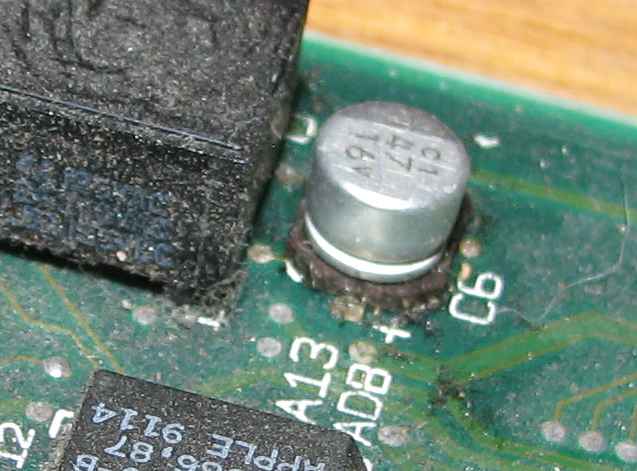
Well, about a month ago, I started thinking about this idea again and decided to go for it. I started out by booting up my old IIcis and deciding which one to hack. One of them had a very faint startup chime, it wouldn’t boot up unless left unplugged for a while, and the hard drive wouldn’t spin up. I decided to hack this one because it was in the worst shape of the two. After checking out the 68k Mac Liberation Army forums, it became clear that the faint startup chime was probably because the electrolytic capacitors on the motherboard had spewed electrolyte all over. I inspected the motherboard and sure enough, many of the capacitors had gunk nearby. Here’s an example of what I’m talking about:

Gross, right? This one happens to be right next to the power button. Perhaps it was causing the power button to work intermittently. Several of the other capacitors looked very similar, and in some cases it appeared that some of the electrolyte had actually gotten onto nearby components. This stuff is nasty and can corrode the motherboard over time, so I knew I had to get it off.

You may notice that these capacitors are surface-mount, and I just got done explaining how I’m not very comfortable with surface-mount soldering. Well, this isn’t terribly complicated soldering. I get nervous when I’m doing components with tens of pins very close together. This stuff wasn’t so bad–there’s a connection on each side, so you really just have to be careful about lifting pads. I did kind of lift one, but it is still electrically connected and everything’s fine. Anyway, I removed all the capacitors (including the through-hole ones as well). I could definitely tell the capacitors were bad when they began smelling like fish as I removed them. After taking them all out, I cleaned the board with 99% isopropyl alcohol (great for cleaning circuit boards! It evaporates almost instantly). I especially went over the areas that looked like the one pictured above. I then put in brand new capacitors.

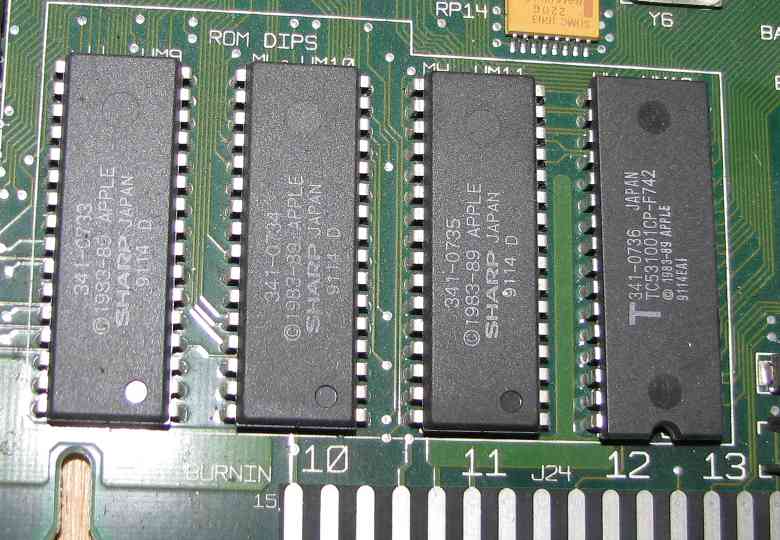
While I had the board out, I removed the four ROM chips:

Removing them was pretty interesting. I did a lot of research on the web to see what other people thought about removing DIP chips in old forum posts, tutorials, videos, etc. The attitude I found online was mostly: “you can save the board or the chip, but not both.” Most suggestions were to cut the old chips out and then easily remove the remnants of the pins with a soldering iron. I also found a few videos of people who had vacuum desoldering guns — in particular, the Hakko 808. The thing had great reviews, so I got one. It’ll be nice to have in my set of tools anyway. It requires a lot of maintenance to keep it working and prevent the pump from getting messed up, but it’s definitely worth it just for the convenience. I really wanted to get the original ROM chips out intact, too, so I’m happy with that. I ran into a bit of trouble with either the ground or VCC pin (can’t remember which) because it takes longer to heat, but other than that, it was pretty easy to use it to remove the chips. I added a bit of extra solder to help the old solder heat up, and the gun sucked most of it out painlessly after that. Sometimes the chips did not lift out easily, even though I couldn’t find any visible solder with my eye loupe. I could tell that the solder was essentially gone, though, so I yanked the chip out with a bit of force to break the miniscule connection the solder still had, and it didn’t damage anything. That may have been stupid on my part, but it worked out for me!

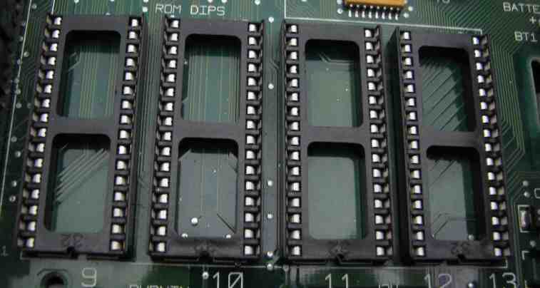
So I replaced the ROMs with sockets:

Then, I stuck the original ROMs back in the sockets, and booted the IIci up. Success! Not only did it boot, but the sound was no longer faint and the power button worked every time, so the capacitor replacement fixed that. However, I knew I’d be using some kind of EEPROM in place of the original ROMs. Notice that one of the original ROMs says it is a TC531001CP. I somehow managed to find a (really old) datasheet for it online and discovered it uses a standard pinout that most 32-pin DIP devices also use.

I found a couple of reprogrammable SST chips of the same capacity which seem to fit the pinout and electrical specs: the SST27SF010 and the SST29EE010. It looks like Greenliant broke off from some of SST’s flash stuff, so they are actually now the GLS27SF010 and the GLS29EE010. I started out with the GLS27SF010. It has a couple of extra pins for programming the chip that are not connected on the IIci’s original ROM, so I had to tie them to VCC on the bottom of the motherboard. The GLS27SF010 was really annoying to program with my Willem programmer, though, because I had to change a jumper on the programmer board any time I wanted to erase it, and remove it to program it. So I switched to the GLS29EE010, which is a lot easier to use, is rated for many more erase cycles, and only has one pin that has to be connected to VCC. I read the contents of the original ROMs, burned the contents to my EEPROMs, stuck them in the motherboard, and it booted!

This completed the hardware portion of my hack. At this point I knew I could reprogram my EEPROMs, stick them in the IIci, and get it to do cool stuff.

I figured out that the four ROM chips are each 8-bit ROMs and the computer itself addresses 32 bits at once. How this works is one of the ROMs is connected to data lines 0 through 7, one is connected to 8 through 15, another is connected to 16 through 23, and the final one is connected to data lines 24 through 31. This means that as far as what the computer sees, to turn the four ROM images into a single ROM image I could disassemble, I had to take one byte at a time from each chip:

Chip 1, Byte 0
Chip 2, Byte 0
Chip 3, Byte 0
Chip 4, Byte 0
Chip 1, Byte 1
Chip 2, Byte 1
Chip 3, Byte 1
Chip 4, Byte 1

I wrote a quick program to do this and was on my way.

In order to get any further, I had to turn to posts by Dennis Nedry on the 68k Mac Liberation Army forums. After following his posts around I was able to discover he had done a lot of the dirty work for ROM hacking. It turns out that Macs have a checksum in the first four bytes of their ROMs, and if it doesn’t match, the Mac won’t start. He had already figured all this out and written code to calculate and check the checksum of a ROM image. Without his work, there’s no way I would have gotten any further — I probably would have given up and just said “whatever — Apple’s protecting their ROM from being modified, I guess I’ll go mess around with something else.” Anyway, he had a ton of useful information here and here.

I started out with the basics and changed an icon. After some crazy searching in the ROM image, I was able to locate the floppy disk icon that appears if you boot a Mac without a startup disk present. There are actually three icons: a floppy disk, a floppy disk with a question mark on it, and a floppy disk with an X on it. When there’s no startup disk present, it alternates between the plain floppy disk and the floppy disk with a question mark. I changed the plain floppy disk icon to a black Apple logo, and the question mark floppy icon to a white Apple logo. Then I recalculated the checksum, split the ROM image into four files, burned them, stuck them into the IIci, and got this:

OK, that’s great! I had proven that I could do it. But then I wanted to move on to bigger and better things–my original goal. The custom startup chime.

At this point, I have to once again thank the people on the 68k Mac Liberation Army forums who gave me some great pointers on what to look for in my post. Trash80toHP_Mini was kind enough to scan a bunch of pages of an old out-of-print Apple hardware book for me as well. Let me tell you, there are some really cool people on those forums!

I started disassembling the ROM code and searching for places that referenced the Apple Sound Chip located at 0x50F14000 (and other repeated addresses as well). It took a while to get comfortable with 68k assembly, but it’s really not that bad. It’s actually kind of nice compared to x86 assembly in my opinion. This site was an invaluable reference. In the middle of this, I installed MPW (Apple’s old software development setup) and happened to discover that it included several Mac ROM maps! The IIci was one of those. I found some interesting labels in the ROM maps called BOOTBEEP, BOOTBEEP6, ERRORBEEP1, ERRORBEEP2, ERRORBEEP3, and ERRORBEEP4. Using that info, I later discovered that the ROM location I was in the middle of disassembling did indeed happen to be the startup chime.

Once I got a clue as to what the code was doing, I figured out a way to play the various chimes provided by writing a Mac app that played them. It turns out BOOTBEEP is just a handler that plays BOOTBEEP6, which is the actual startup chime. ERRORBEEP1 is the minor chord that plays in the chimes of death before the arpeggio. ERRORBEEP2 is a weird tone I had never heard before. ERRORBEEP3 is that same tone, with another note added at the end. ERRORBEEP4 is the familiar arpeggio error chime.

Each one of these sounds is a structure in the ROM that is passed to a ROM sound synthesis function that plays it using the Apple Sound Chip. When you hear the chimes of death, it’s actually playing two sounds consecutively: first ERRORBEEP1 for the chord, then ERRORBEEP4. After doing some serious disassembly of the sound synthesis function, I more or less understand what it does. The MAME source code was extremely useful to help me understand some of what the function was telling the Apple Sound Chip to do.

The synthesis function uses the wavetable synthesis capability of the sound chip. It is given one to four frequencies to play. It also is given several time values. One tells it how long before the wavetable should be updated. I believe it essentially specifies how quickly the waveform evolves and eventually fades out to nothing. Another time value sets how many steps should occur between playing each of the frequencies it’s given. Once a frequency is playing, it leaves it running and starts the next frequency in another voice. So at the end of the chord, all four voices are playing. If you make this a small number, it will play them all close together and it will be a chord like the startup chime. If you make it a large number, it will play them spaced apart, more like the death chime arpeggio. There is also a time value that specifies how long the sound should play in total. This would allow you to keep the sound going for a while after all the notes are playing. The frequencies are specified in terms of a 24-bit fixed-point increment value, basically telling the wavetable synthesizer how many entries in the wavetable to skip each time it reads a value. This effectively changes the frequency of the sound that plays based on what you set the increment value to.

It may sound complicated (it is!) but what it comes down to is this: the startup chime on a Mac IIci takes up 32 bytes of ROM space (not counting the synthesis function, which is reused for all the other startup sounds like the error chime). That’s pretty impressive, and you can see why they went that route to save ROM space.

So, here’s some info on the structure of a synthesized sound in the ROM:

  • A 16-bit number that seems to specify some kind of a volume setting.
  • A 32-bit number that sets how fast the waveform changes (a “step length” perhaps?)
  • A 32-bit number that sets how many steps elapse before starting to play the next frequency in the list of frequencies
  • A 32-bit number that sets how many steps before the sound is done.
  • A 16-bit number that specifies the number of frequencies (maximum of 4, since the sound chip has 4 voices)
  • For each frequency, a 32-bit number that contains the 24-bit fixed-point increment value I described earlier. The top 8 bits are not used.

Once I figured all this out, I just had to find some space in the ROM to put my Mario tune. I found what appears to be 35 KB of empty space, filled with many repetitions of an Apple copyright notice and a date. I made several of these sound structures for all the different chords I needed to play, and stuck them in there, along with code to play them in the correct sequence. I then modified the startup chime code to jump to my code instead. Here are the results:

Yes, that’s right. a Super Mario Bros IIci. It reboots after the first Happy Mac because I don’t have a PRAM battery installed on the motherboard. After that it continues booting fine.

I’d like to figure out how to make it play a sampled startup sound, but it may be difficult to figure out how to set up the sound chip for that mode. (Forget that, I now have sampled startup sounds working!) Anyway, let me know if you have any questions and I’ll try to answer them…and thanks again to everyone who helped me out with this project either directly or indirectly!

P.S.: Remember how I said the hard drive wouldn’t spin up? Well, I found a really, really old newsgroup posting online where someone with the exact same drive model had the exact same problem. The advice given? Give it a smack (not too gentle, but not too rough either) while it’s powered up. I hit it with a screwdriver and sure enough, it started spinning up. It’s been fine ever since through many power cycles! All the data was still intact. I certainly wouldn’t try that trick with the hard drives we have today, but I guess with stuff from the lower-density storage era, it’s not a terrible idea!