I recently released a big update for my Mac ROM SIMM Programmer software which is written using Qt for cross-platform compatibility. As part of the update I wanted to release the Mac build as a universal x86_64/arm64 binary so that M1/M2 Mac users would be able to run it natively. It doesn’t currently compile for Qt 6, although I think I can fix that in the future without too much effort. However, Qt 5.15.9 and later do support creating universal binaries out of the box, so I decided to figure out how to set it all up.
Even though I think I have pretty decent Google-fu, it was difficult to piece everything together to accomplish this goal. I’m hoping this post can serve as a reference for people in the future. These instructions are based on Qt 5.15.10 because that is the latest version of 5.x that is currently open source. I did this on an M2 Mac Mini running macOS 13.5.1 Ventura.
First of all, before anybody suggests it, you can’t use homebrew to install Qt for this because it doesn’t supply a universal build of Qt. If you’re going for an open-source build, you will need to build your own Qt instead. I’m assuming people with a commercial license can just get compiled binaries from Qt. So if you have access to that, you can probably skip the step of building Qt. Otherwise, follow along with me…
In the previous post in this series (here are links to parts 1, 2, 3, 4, and 5), I really got the Chumby to start looking like a Chumby. The display was alive! But getting the LCD controller working was really only one puzzle piece when it came to the display. The backlight needed more work so that I could control the brightness, and the touchscreen controller is a completely nonstandard design that is specific to the Chumby.
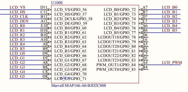
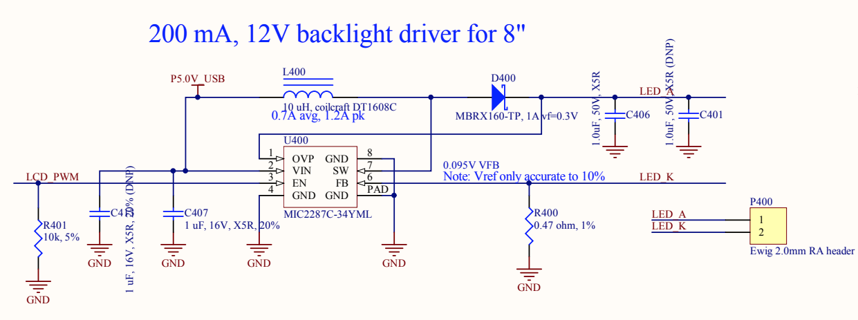
Let’s start with the backlight. This should be pretty straightforward, right? Looking at the schematics, the backlight control is connected to GPIO_84 (also known as PWM_OUT1) on ball A4 of the PXA166. I already knew that I could turn the backlight on full blast by using this pin as a normal GPIO pin and driving it high. That’s what I did in the previous post in order to quickly get it working.
A couple of months ago I stumbled upon a post on Hackaday about an inexpensive open-source USB 2.0 sniffer created by Alex Taradov. This is a really cool project! Normally, USB sniffers like this can cost thousands of dollars, especially if you’re paying for fancy protocol decoding and also want high-speed 480 Mbps support. This one costs about $50 in parts to assemble yourself, although it will take hours to solder and you will need some experience with hot air (or reflow oven) soldering since the USB PHY is a QFN chip with an exposed pad underneath.
I actually have an Ellisys USB Tracker 110b that I bought on eBay many years ago, but it only does low-/full-speed decoding. I thought this would be a good opportunity to upgrade my capabilities to also be able to handle high-speed USB sniffing, while also providing some good soldering practice.
Here’s my (very long) video about the process of building up one of these and programming it. I left in all the mistakes I made along the way. Why not show the world that it’s normal to make dumb mistakes when you build stuff?
I thought I’d use this post to explain in a little more detail what exactly a USB sniffer is. Why would I buy (or make) a hardware USB sniffer when Wireshark already has software USBPcap support in Windows?