In my last post, I figured out how to use Apple’s leaked Flasher utility from the 1990s to reflash a ROM SIMM inside of my Performa 630. It’s basically the Mac equivalent of a BIOS update, but only for Apple’s developers. The research involved in that post was quite a journey of reverse engineering from both a software and hardware perspective. I had to disassemble the code to figure out which computers were compatible and what the software was expecting to find. I also had to create a replica of an Apple development ROM SIMM that was wired exactly the way Macs of the era expected it. Although I was very excited about my discoveries, one big question remained:
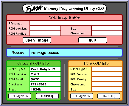
What was the purpose of the bottom right half of the main window labeled “PDS ROM Info”? And what would it take to enable it?
After I wrote about the possibility of programmable Mac ROM SIMMs in Quadras a couple of months ago, I suspected that there had been a way for developers at Apple in the 68k Mac era to reflash the ROM in their Macs during development, just like BIOS updates on PCs. The reason I believed this is because the ROM SIMM socket in the Quadras brought out pins for 12V (VPP) and write enable (/WE). I had verified that the write enable pin was going into the memory controller chip in several Mac models, so I was pretty confident that in-system programming was possible.
As luck would have it, multiple people pointed out to me that an Apple internal utility used for ROM flashing had been uploaded to the Macintosh Garden. It was recovered from a prototype PowerBook 520 purchased in 2020. Of course, I had to download this utility and figure out how it works.
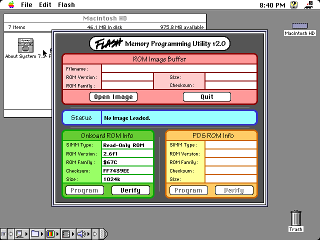
I ran it on my LC 475 and this is what it looked like:
TL;DR: The pinout of modern programmable Mac ROM SIMMs needs to be changed for correct operation in Quadras. If you’re interested in how I reached that conclusion, or at least want to see some cool pictures, read on below.
One thing that you usually discover when searching for info about these programmable ROM modules is that they’re compatible with the earliest 68030-based desktop Macs: the SE/30, IIx, IIcx, IIci, IIfx, and IIsi. The most common use of them is to set up a special custom bootable ROM disk using Rob Braun’s driver, Big Mess o’ Wires’ driver based on Rob’s, or Garrett’s Workshop’s driver. In general, the compatible ROM images out there are all using the IIsi ROM which is capable of booting any of the aforementioned Macs.
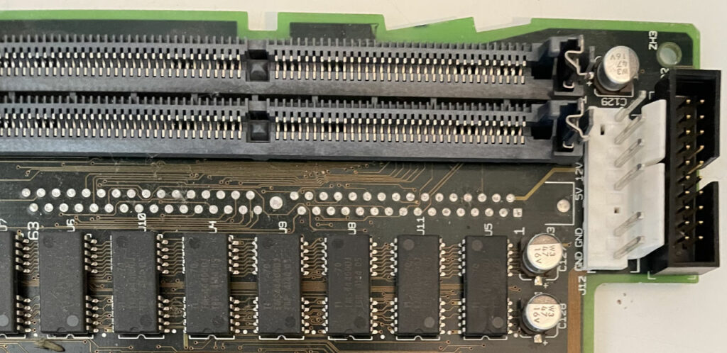
What you may not know is that most of the later 68k Macs also have provisions for a ROM SIMM socket, but aside from the very first Quadras (700/900/950) which always have the socket installed, it’s not usually populated. Some early production or prototype units have it, but most just have empty through-holes filled with solder where the socket would go.
Don’t worry, I already replaced those leaky capacitors before they had a chance to damage the board.
Several months ago, Will from CayMac Vintage reached out to me looking to resurrect my old Mac ROM SIMM programmer project. As a quick summary of that project, it provides a convenient way to program custom 64-pin ROM SIMM modules for vintage Macs from the late ’80s to early ’90s. There are several reasons you might want to do this, including: replacing an original ROM module that has gone bad, disabling the startup RAM test to decrease boot time in systems with a lot of RAM, bbraun’s amazing bootable ROM disk hack, or my startup chime hack. JDW recently made a cool YouTube video explaining custom ROM SIMMs if you’re curious about them. He even included some footage from 2003 of me playing basketball!
I used to make programmer boards and programmable ROM SIMMs and sell them to hobbyists, but it burnt me out. In particular, assembling the boards and the logistics of shipping were not fun to deal with. Thankfully, in 2016, Steve from Big Mess o’ Wires stepped in to take over. He made his own customizations to the programmer and made some really neat improvements to the bootable ROM disk driver. He still sells the Mac ROM-inator II SIMM to this day, but he stopped selling the programmer board. In the meantime, many other players have entered the market with custom ROM SIMMs, but nobody has been making the programmer available to the community, likely due to my non-commercial license on the PCB design.
Will was looking to fill that void. I helped him get going, but we discovered that the AT90USB646 microcontroller that I originally used was hard to find due to the chip shortage. At the time, it was easier to find the AT90USB1286 instead, which is essentially just the exact same chip, but with 128 KB of flash instead of 64 KB of flash.
If you’ve been reading my blog for a while, you might remember back in 2012 when I changed the startup sound on my Power Mac G3 (Blue and White). That was a fun introduction to the Forth programming language. I had to reverse-engineer just enough of Apple’s firmware update script to understand what was going on.
Recently, Aidan Halpin, a reader of this site, asked me if I could do the same kind of startup sound customization on his iMac. This particular iMac is officially known as the “iMac (Slot Loading)” and has a model identifier of PowerMac2,1. As you can guess from the name, it has a slot-loading CD-ROM drive unlike the original iMac that had a laptop-style tray-loading drive. By the way, Aidan’s iMac is special because it has a PowerPC G4 processor soldered onto the logic board instead of the original G3.
These SIMMs (and programmers) are available for purchase here.
As you may have seen from my previous posts, I have developed a programmable ROM SIMM for older Macintosh computers and a programmer to go with it. Everything from the hardware design to the firmware is completely open source. The combination is pretty nifty and enables people to do all kinds of crazy things that previously weren’t possible.
I always figured that the 2 MB size of the SIMM was plenty — I never really envisioned using the custom ROM SIMM for anything other than customizing the startup chime. However, bbraun came up with an even better idea — a ROM disk driver! He has patched the IIsi ROM (which should be compatible with the SE/30, IIx, IIcx, IIci, IIfx, and of course the IIsi itself) to enable booting from a ROM disk that uses up the remaining space on the SIMM and also has some other tweaks like disabling the slow RAM test that the previously-listed machines perform on every cold boot. It works perfectly and allows you to create a 1.5 MB bootable ROM disk to append to the 512 KB IIsi ROM. It boots up extremely quickly!
After he came up with that brilliant idea, I figured I should maximize the potential size of the disk image. The 64-pin ROM SIMM slot has 23 address pins labeled A0 through A22. However, A0 and A1 are unused due to the fact that the data bus is four bytes wide, so there are really only 21 usable address pins. That provides for a total of 221 = 2,097,152 = 2*1024*1024 usable addresses. Each address points to 4 bytes of data, which provides for a total maximum ROM SIMM size of 8 MB. After taking into account the 512 KB ROM size, that would leave 7.5 MB of usable space for a ROM disk.
You can probably see where I’m going with this–I designed a bigger ROM SIMM!
First of all, I had to find NOR flash chips that ran on 5V and were big enough. It turns out that 5V chips are becoming harder and harder to find, especially in larger sizes. Everyone is moving toward 3.3V and lower. After a ton of searching, I settled on the Micron M29F160FB5AN6E2, a 5V 16-megabit chip that can be accessed in parallel using either a 16-bit data bus or an 8-bit data bus. It’s designed with automotive applications in mind, which probably explains why it still exists as a 5V chip. 16 megabits (Mb) is equal to 2 megabytes (MB). In order to reach the full 8 MB size, I need four of them per SIMM. I use them in 8-bit mode so each of the four chips provides one of the four bytes per address, just like how I designed the 2 MB version of the SIMM.
The chips are available in a fine-pitch TSOP package, which pretty much eliminates the possibility of socketing them. These chips really need to be soldered down, so this new SIMM requires my programmer board in order to put a disk image onto it. Here is the final product:
Some newer machines like Quadras have pads on their motherboards for these SIMMs–you just have to solder on your own socket. Unfortunately, it’s looking like they are hardwired to only address 1 MB of ROM space. Unless someone discovers a way to get around that, those machines will probably not be able to take advantage of the ROM disk. So for now, this ROM disk is restricted to the SE/30, IIx, IIcx, IIci, IIfx, and IIsi.
I actually completed this project a few months ago, but never got around to writing a post about it. Now I’m ready to share it!
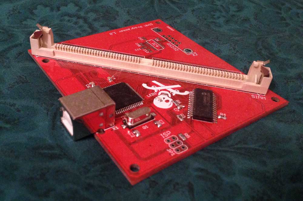
Remember the programmable Mac ROM SIMM I created earlier? It’s nice and all, but it’s extremely annoying pulling the four chips out of their sockets and reprogramming them one by one. Having to do that over and over again will get old really fast, not to mention the fact that you need an EEPROM/flash programmer. I recognized these problems and solved them by creating a USB programmer board for the SIMMs. You take the SIMM out of the Mac, put it into the programmer’s SIMM socket, plug the programmer into a USB port on your computer, and then run a program I developed that can write or read the SIMM. The software works with Windows XP and newer, Mac OS X 10.5 and newer (Intel only), and Linux.
The ROM SIMM is compatible with the following Mac models: SE/30, IIx, IIcx, IIci, IIfx, IIsi, and Quadra 700. Anything from that era with a 64-pin ROM SIMM socket should work fine. The Quadra AV models, some of which have a 64-pin ROM SIMM socket, do not work with the SIMM. The pinout is different.
Although there aren’t currently any automatic ways to patch in a custom startup chime (this is planned though!), this board can still be useful if you want to tinker with the Mac’s ROM or make a replica IIfx or IIsi ROM SIMM to make your SE/30, IIx, or IIcx 32-bit clean.
Here’s what it looks like with one of my programmable ROM SIMMs in it:
Credit goes to olePigeon on the 68k Mac Liberation Army Forums for creating the Jolly Roger graphic used on the SIMM and the programmer board, and for providing the 64-pin SIMM sockets (which are incredibly difficult to find). Also thanks to others on the same forums for giving me PCB layout tips and helping me debug a scary problem that turned out to be a software error (thanks ojfd, bigmessowires, and Dennis Nedry!).
The board uses an AT90USB646 microcontroller as its brains. It has hardware support for USB, which is pretty cool. I also added an MCP23S17 GPIO expander chip to give me enough pins to control all of the SIMM pins at the same time (the microcontroller by itself did not have enough pins)
I had to make a small change to the ROM SIMM to make it writable. On the first revision of the SIMM, the write enable pin on each flash chip was tied directly to +5V, forcing the chip to always be in read mode instead of write mode. In the new revision, I’ve repurposed one of the +5V pins in Apple’s SIMM pinout to be the write enable pin. Because it’s +5V in Apple’s pinout, it’s always tied high when it’s in the Mac (thus disabling write mode), but when I put it in my programmer, I can control whether it’s high or low. I think that’s originally what the pin was designed for (it’s directly next to the output enable and chip enable pins, so that makes logical sense). Anyway, my point is that my original ROM SIMM (which doesn’t have the Jolly Roger picture on it) is not compatible with this programmer. I only had 12 of those boards made, so there aren’t many out in the wild 🙂
Everything I’ve done for this project is open source, from the PCB layouts to the programmer firmware to the control software. I’ve made extensive use of other open source stuff for this project, so I should probably share everything that I used for creating this project:
Qt — a cross-platform library that I used for creating the control software.
QextSerialPort — a Qt library for interfacing with serial ports–I originally used a custom version that allows Linux device discovery and fixes a device discovery bug on Windows, but issues were fixed in the main project at some point. The SIMM programmer appears as a virtual serial port to the computer, so that’s why I use a serial port library.
LUFA — An extensive USB library for AVR microcontrollers. It’s really amazing. Without this project it would have been ridiculous trying to make the programmer firmware. It made it very simple to create a virtual USB serial port on the AVR.
All of the code, compiled binaries, and PCB schematics/board layouts are available on GitHub.
Important notes:
Don’t plug/unplug the SIMM from the programmer board while the programmer board is powered. I didn’t add any protection and I’m pretty sure it would be ridiculous to try to protect against that stuff. Just play it safe and only plug/unplug the SIMM while the programmer board is unplugged from USB. It’s OK — the programmer software stays completely happy if the board is plugged/unplugged while it’s running.
Make sure the SIMM is pressed firmly onto the board. Some of the SIMM sockets don’t perfectly fit the SIMM, but they should still work if everything’s pushed in firmly. If it’s too loose, I’ve seen some of the chips fail to read and write properly.
If you suspect something is messed up on a SIMM, the software provides an electrical test function to make sure none of the SIMM pins are shorted to each other (with the exception of shorts to +5V — sorry, can’t test that without pull-down resistors!). You can also click a button to electronically read manufacturer and device info from the flash chips to verify that they are responding correctly.
Just to be clear, this board is NOT capable of programming stock Apple ROM SIMMs. Those SIMMs use mask ROMs which are not programmable. If you’re careful, you may be able to read those SIMMs (do NOT try to do anything that does a write cycle, though–you may damage the programmer, the ROM SIMM, your computer, or any combination of the three). To be safe, only use the programmer with my programmable ROM SIMM.
As I mentioned earlier, the board is also not capable of programming my initial version of the ROM SIMM that did not have the Jolly Roger graphic on it. If you have the old version of the SIMM, do not try to program the SIMM in the programmer board — it won’t work and you might damage something.
As you may recall from the past, I’ve taken a Mac IIci and hacked a new startup sound into it. Then, later, I actually had a programmable ROM SIMM PCB manufactured that works with many Macs from the late 1980s and early 1990s. I have yet to talk about it on this blog, but I have also created a USB programmer for the ROM SIMMs. Maybe I’ll create a post about that later. My post today is about another startup sound hack I’ve just completed. I have a video below, so check it out!
I’ve moved on to the next stage of my Mac ROM startup chime hacking, toward the late 90s to mid 2000s machines — the New World PowerPC machines. These computers are powered by the PowerPC G3, G4, and G5, starting with the original iMac. They call them “New World” because they use a totally different style of ROM from previous Macs. They have a 1 MB boot ROM on the logic board which does the initial setup of the machine. The boot ROM also provides Open Firmware which gives them a lot of flexibility for doing things before the operating system has loaded. Open Firmware is capable of loading a file from the hard drive (typically called Mac OS ROM) which contains the rest of the ROM that older machines had on a mask ROM chip on the logic board.
I discovered that the startup chime on these Macs is also stored in the 1 MB boot ROM. I have several New World Macs, and they all have the exact same startup chime. I played around with the ROM from my G3 Blue and White by opening a dump of it as raw sound data in Audacity and found the sound, but I could tell it was compressed. After some detective work combined with lucky guesses, I figured out that the sound is a chunk of 58,548 bytes compressed using Apple’s version (IMA 4:1) of the IMA ADPCM compression format. The uncompressed sound is a 44.1 kHz, 16-bit mono sound that is just under 2.5 seconds long–so anything that is 2.5 seconds or shorter should work fine as a replacement. I’ve looked at the ROM from all of my other New World Macs, and the sound is stored in the exact same format in all of their ROMs as well. I would venture a guess that it’s stored in that exact same format in all New World Macs.
OK–so at this point, I knew it could be done. My past customization experiments have required hardware modifications to change the chime. These machines are different, though–the “boot ROM” (as I have been calling it) is actually a flash chip that can be programmed in-system. Apple created firmware updates for several of the New World Macs. The firmware update just re-flashes the chip with new data. I could desolder the chip, reprogram it, and solder it back on, but why bother if there’s a way to do it directly from software? So I grabbed Apple’s G3 Firmware Update 1.1 and inspected it. It’s just an Open Firmware Forth script that contains the new ROM data to flash to the chip. It has code for programming flash chips made by several manufacturers. I wasn’t very familiar with Forth (and still don’t know it very well), but I went through some excellent tutorials to get a basic feel for the language. The data to be flashed is encoded using a variant of Ascii85 encoding and there are several Adler-32 checksums to confirm the file’s integrity.
After mcdermd from the 68k Mac Liberation Army forums was kind enough to send me a few spare logic boards for my G3 (I didn’t want to mess with my existing logic board), I went ahead and injected my own chime into the firmware update file. This required encoding a sound (I used the old startup sound used by the Quadra 700 and newer 68030 and 68040 Macs) in IMA 4:1 format, overwriting the old sound with the new raw sound data, re-encoding the ROM in Ascii85, and recalculating all of the Adler-32 checksums. I also had to patch Apple’s firmware updater program to force the firmware to always update even if it thinks the firmware is already up to date.
I did the firmware update procedure in Mac OS 9 after patching all of the programs, and sure enough, everything worked fine! Here’s a video:
This technique will probably work for all other New World Macs–everything from the original iMac up through the G5s before Apple switched to Intel processors. Some of these machines never got a firmware update from Apple, though, so it may be difficult to figure out what the Forth script should do for controlling the flash chips in them. Hopefully it stayed pretty consistent across the various models, but I just don’t know at this time. It looks like some of the newer firmware updates no longer use Ascii85 encoding, so things definitely changed in the firmware updaters as time went on. Oh well–this is a start!
Someday in the (hopefully near) future I will document everything I had to do in more detail and maybe automate it with some scripts. Because I have to mess with both the data fork and resource fork of files, I won’t be able to automate it all on a Linux or Windows computer, I think. But I can at least automate creating the data fork that will need to be injected into the firmware update file and provide instructions for using ResEdit to patch the firmware updater utility.
Update:
I am releasing the code I used to patch the chime in the G3 Firmware file bundled with the latest version (1.1) of the Power Mac G3 Blue & White firmware updater. If you want to do this for yourself, download the code and compile it on a Linux or Mac OS X machine with g++. It’s a command line utility that can patch the original G3 Firmware file with a new startup chime. The comments in the code should explain everything. Use Audacity to make a raw 44.1 kHz 16-bit big endian sound file to encode using this tool. When you’re finished, put it onto a Mac and use BBEdit Lite to copy the data fork of the newly patched file onto the original G3 Firmware file. Finally, you will need to patch the firmware updater program’s data fork in order for it to recognize the newest firmware as a valid update file. See what I said in my 68kmla forum thread. Once that’s done, you can run the updater program. After the update is done, it may complain at every boot that the firmware update was unsuccessful. If this happens, just remove the firmware updater program from your startup items, or replace the firmware updater program with the original and reboot once more time.
BEWARE: If you have a G4 chip in your G3, this firmware update will disable compatibility with the G4, rendering your system unbootable without a G3 processor installed. I haven’t yet figured out how to integrate the G4 enabler patch that G4 upgrade kits included. For now, only do this if your system has a G3 processor in it.
BEWARE #2: Doing this procedure can brick your computer if something goes wrong. Do this AT YOUR OWN RISK!
I hope to make the process more seamless in the future, but for now, if you know how to compile code and can mess around with data forks of files, and you’re willing to take a risk that your computer might be bricked, it’s worth a shot. I do not have the knowledge to make this work on any New World Mac. For now, it’s only limited to the blue and white G3.
I haven’t written about my Mac ROM hacking lately, so this post will double as an update to my ROM hacking endeavors and a review of Seeed Studio‘s awesome Fusion PCB service.
After going through all the hoopla to desolder the DIP chips on my Mac IIci and socket them, I finally got frustrated. The main annoyance is that the DIP ROMs are all the way underneath the hard drive and floppy drive carrier. It was forcing me to basically rip everything out of the IIci in order to access the DIP sockets. I also had been in contact with the folks on the 68k Mac Liberation Army forums, and they had a lot of useful information, including the tidbit that many of the Mac II series machines (and the SE/30) have a SIMM socket that you can put a ROM SIMM into. My IIci also has this socket, and it’s easily accessible without removing anything from the case. So, I decided to make my own! Thanks to a lot of advice from fellow forum members, I was able to lay out a SIMM printed circuit board to have manufactured.
I ran into a problem: the SIMM needs to be about 0.047″ thick in order to physically fit in the socket. Most of the inexpensive circuit board prototyping manufacturers make boards that are 0.063″ thick. Luckily, bigmessowires from the 68k Mac Liberation Forums was able to recommend a PCB manufacturer that could make the boards in the thickness I needed: Seeed Studio Fusion PCB. He had used them in the past with good results, so I went for it.
Seeed Studio has amazing pricing. My board was about 3.85″ by 1.1″. That fits within a 10 cm by 5 cm rectangle. As of this writing, they can manufacture ten 2-layer boards of that size for a total of $24.90 plus shipping. That includes solder mask and silkscreen on both sides. It’s an incredible price! They also offer many thickness options, including 1.2 mm, which works out to 0.047″. I asked for red solder mask instead of the standard green, which added an additional $10 to the price. They have extremely good trace width/spacing requirements: 6 mil (0.006″) trace width and 6 mil spacing. I went ahead and made my minimum trace width and spacing 8 mils, just to be safe.
After you place your order online, you e-mail them a zip file containing the Gerber files for your PCB. If there are any problems, they will let you know — otherwise, you just have to wait for the boards to be manufactured and shipped.
Shipping was only $3.52 for registered air mail to the United States from Hong Kong. They had other options, too, but this was the least expensive one. They take PayPal as a payment option, and I can’t remember the other options they offered. I placed my order on the night of Monday, September 5, they shipped my board on Tuesday, September 13, and the package arrived on Friday, September 23.
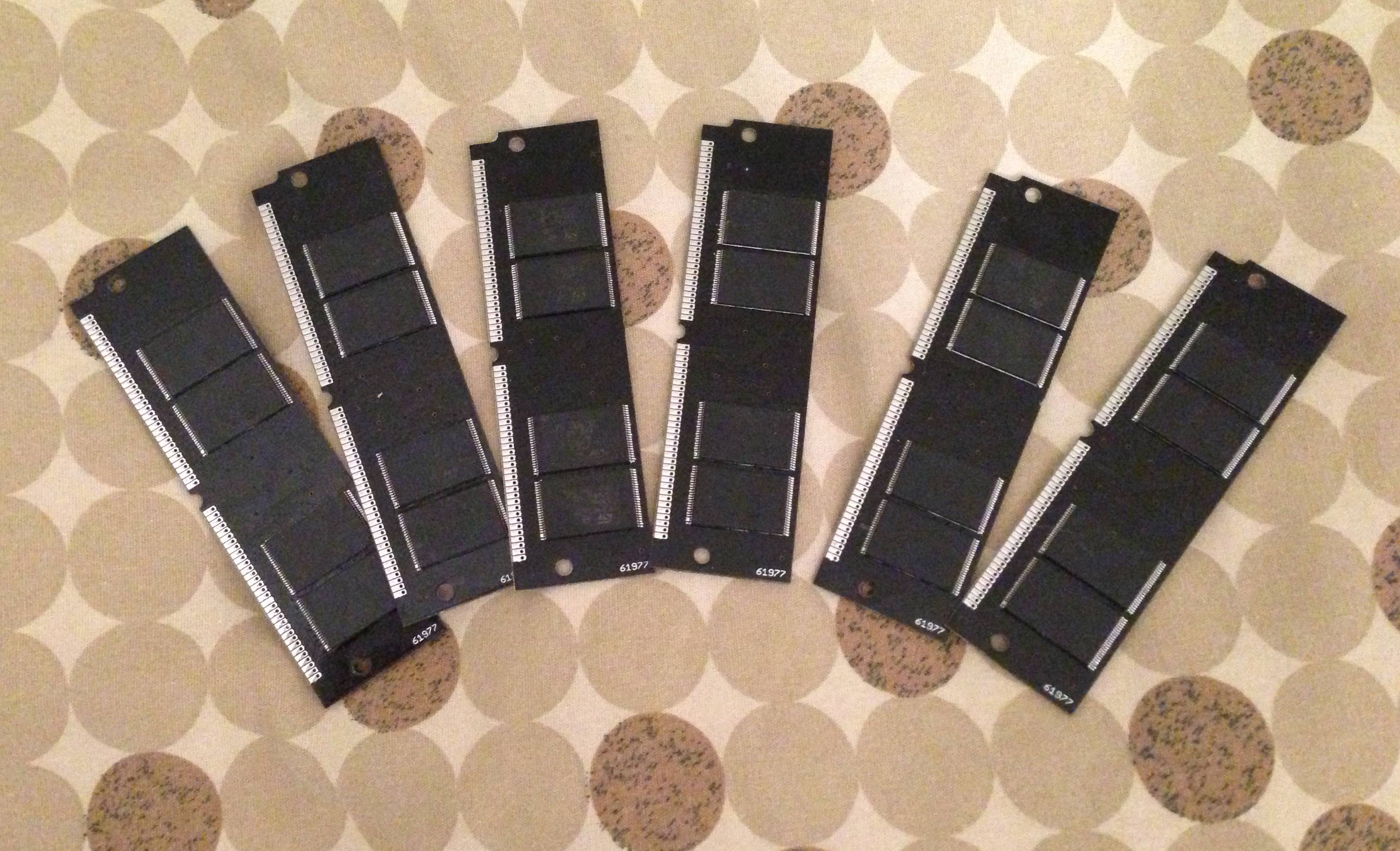
I’m sure you’re wondering: how did the boards turn out? Well, they turned out just fine! As you can see, they were able to manufacture a board with an irregular shape:
You may see some numbers on the silkscreen. Seeed Studio’s directions tell you to add your order number to the silkscreen somewhere, so I did that on the bottom. They also added a few other numbers onto the top silkscreen. Not a big deal at all, especially for the price!
Electrically, the SIMM tested fine. All the traces were perfect. Seeed Studio will electrically test 5 of your boards for free, and you can pay to have the other 5 tested, too.
Oh, did I mention that they actually sent me 12 boards instead of 10? How cool is that?
I would highly recommend them if you are looking for budget PCB fabrication. They only do 1 or 2 layer boards, so you can’t do anything overly fancy with 4 or more layers, but 2 layers is plenty for all kinds of fun stuff you can make, such as this SIMM.
By the way, my SIMM ended up working perfectly, and it expanded my IIci’s ROM capacity to 2 MB (the original ROM is only 512 KB). I naturally tested the rest of the capacity by filling the remaining 1.5 MB with the Super Mario Bros music and turning it into the longest Mac startup chime ever:
If you’re curious what the assembled board looks like, I show it off briefly in the video.
So anyway, all in all, I had a very positive experience with Seeed Studio’s Fusion PCB service! I was shocked when I saw the pricing, and I am very happy with the boards I got back. Thanks, Seeed Studio!
In my last post, I wrote about how I had figured out how the Macintosh IIci’s synthesized startup sound works. I talked about how I replaced the ROM chips on the motherboard with sockets and disassembled the ROM code. I shared a video showing how I customized it to play the first few notes from the Super Mario Bros song. At the very end of it, I talked about how it would be awesome to figure out how to play a sampled sound at boot time, which would allow me to play any sound I wanted, limited by space available in the ROM. I didn’t feel very optimistic about getting that done, but after a ton of reading, experimentation, and frustration, I have figured it out, and my IIci now plays a sampled startup sound when it boots up. I’d like to share how I did it, as well as provide instructions on how to patch your own IIci’s startup sound with the sound of your choosing.
Before I start, I’d like to thank the people in the 68k Mac Liberation Army forums for the help and encouragement, and also the people who coded the MESS emulator for leaving a very handy register reference for the Apple Sound Chip in their source code. Without any of the aforementioned people, I would never have been able to get this far in my hacking!
Here’s are some videos, followed by how I did it and how you can do it. I decided to inject one of the sampled startup sounds from the LC/Performa series into my IIci:
And here is the sampled startup sound from the 5200/5300/6200/6300 series Macs:
How I did it
To begin, I disassembled an LC III ROM dump. The LC III is one of the oldest Macs that has a sampled startup chime. Its sound chip is not quite the same as the IIci’s, but the way it plays its sampled sounds at boot time gave me a few clues. To write sampled sounds to the Apple Sound Chip, you basically just keep writing samples, one at a time, as long as there is room in the chip. You determine whether there’s room in the chip or not by reading a status register.
So based on how the LC III did it, I wrote a program to test playing a sound by talking directly to the sound chip on my IIci. It failed miserably for two reasons:
The bits of the FIFO status register in the sound chip act slightly differently on the LC III compared to the IIci
When I’m booted into the Mac operating system, there are interrupts looking at the status of the sound chip. An interrupt can grab the FIFO status before I get a chance to see it, and then I’m stuck waiting in an infinite loop for a bit to change, even though it already changed long ago.
No biggie though! First of all, I decided to forget about the FIFO status register completely, and instead I made my program write samples blindly to the chip, adding a pause occasionally to give the chip some time to play the samples and clear space in its FIFO. I messed around with my delays, and I eventually was able to get it to mostly work. By mostly, I mean sometimes it would make some crackly sounds while playing the sound I wanted it to play. I figured this was because interrupts sometimes made my delays longer than they should have been, causing the FIFO to empty out for a short time. My main goal was accomplished though: I knew how to tell the chip to play sounds.
The delay code was lame, though. It makes more sense to listen to what the chip is telling me, rather than guess the status of the chip based on time delays. To solve problem #2, I disabled interrupts during my program. This helped immensely because it prevented the operating system from talking to the sound chip behind my back. Next, I started playing with the status bits to see when they come on and turn off. It was here that I discovered problem #1: The IIci’s sound chip doesn’t behave the same way the LC III’s code implies its sound chip behaves.
The LC III’s code always waits for one of the FIFO status bits to be “1” before it writes a sample to the chip–even the very first sample. The MESS source code says this bit is a “FIFO half empty” status bit. On the LC III, it looks like this bit is 1 any time the FIFO is anywhere between completely empty and half empty. If it’s more than half full, the bit is zero. On the IIci, though, this bit stays at zero, and only becomes 1 once you have filled the FIFO more than half full and it has dropped back down to being only half full by playing enough samples. Plus, once you read the bit, it goes back to 0 until the FIFO has filled more than half full again (and dropped back down to half full after that, which sets the bit at 1 again). This explained why my first attempt failed — an interrupt probably read the status bit’s 1 value (bringing it back to 0 in the process) and I was stuck waiting to see it and never did.
Once it’s finished writing all the samples to the chip, the LC III’s code waits for another status bit to be 1 before continuing on. I’m guessing that this other bit acts as a “FIFO is completely empty” bit, so it’s allowing the code to wait until the FIFO has totally drained out. I don’t know for sure, but that would make the most sense based on what the code is doing. On the IIci, though, according to my tests, this bit is zero until the FIFO is completely full. Then it becomes 1 until you read it, and it resets back to zero immediately.
Based on this information, I decided on an algorithm to use with the IIci to play sampled sounds driven totally by the two status bits:
Check the “FIFO is full” bit.
If the FIFO is not full (the bit was 0), write the next sample to the chip and start over again at the top.
If the “FIFO full” bit was 1, then wait until the “FIFO is half empty” bit comes on, then write the next sample to the chip and start over again at the top.
So the algorithm starts with the FIFO completely empty, fills it completely up, then waits for it to become half empty again, fills it completely up, waits until it’s half empty, fills it up, and so on, until it’s done.
I couldn’t find a way to determine that the FIFO was completely empty, though–so I may be cutting off the end of the sound. I’m not sure about that yet. I don’t notice it, but it’s possible that the sound I’m playing has some silence at the end of it anyway.
So after getting it working in a simple Mac program, I injected the code into the free space in the IIci’s ROM and patched the ROM to jump to my routine instead of the normal startup chime. After a monumental screwup where I accidentally commented out a single line that caused the whole thing to fail and had me puzzled for hours, I got it to work on my second try!
A couple of days later I tried another sound. The 5200/5300/6200/6300 startup chime is actually sampled at 11.127 KHz, which is half the Apple Sound Chip’s standard sample rate. So to play it, I changed my code slightly to write each sample into the sound chip twice, doubling the effective sample rate to 22.254 KHz. This also lets me use a sound twice as long!
So that’s my background info on how I did it. Now…I’m sure you’re chomping at the bit to do it yourself, right?
How you can do it
You need:
A working Mac IIci
Some soldering and desoldering skills
Four 32-pin 0.1″ pitch DIP sockets
Four pin-compatible EEPROMs (I used the Greenliant GLS29EE010)
An image of your Mac IIci’s ROM — read it from the chips after removing them or read it from the Mac before you tear it apart. (Do NOT ask me for ROM images – I’m not interested in infringing on Apple’s copyright)
An EEPROM burner compatible with the EEPROMs you choose and a computer that it can talk with — most likely it will be a Windows-based computer with a parallel port.
The ROM patches I will provide below
A hex editing utility to stick the patches where they belong (I used HxD)
A tool to recalculate the ROM’s checksum after your modification. Ben Boldt’s Mac ROM Checksum verifier will help you figure out what the checksum should be (nice work Ben!) — note: if you run this program on Windows, change the code so that it opens the files in binary mode. Otherwise it won’t work because it will do weird stuff with bytes that happen to be carriage returns and line feeds.
A tool to split the ROM file into four interleaved segments for burning. I made one for .NET that also does the checksumming but I don’t have time to upload it yet…if you don’t want to wait, make a suitable tool yourself! 🙂 See my previous post for info on how the ROM chips are interleaved.
All right! As far as hardware goes, desolder the old ROMs and remember where each one goes. Solder sockets in their place and put the original ROMs into the sockets to make sure that it still boots OK. Each EEPROM will have at least one extra pin that was not connected on the IIci’s original ROM. It will need to be connected to something and not left floating. See the datasheet of your chip to determine what it should be connected to for “read mode”. In the case of the GLS29EE010, it is a pin right next to VCC that is used for programming (the pin is called WE#), and in read mode it is supposed to be pulled high. How convenient! On the bottom of the motherboard, you can blob solder between these two pins to connect them and it should work well–at least for the GLS29EE010!
Now, read the ROM files onto your computer (or use the image you read from the Mac before tearing it apart and split it into 4 interleaved files). Burn the four ROM segments onto your EEPROMs, stick them in place of the original ROMs, and make sure the IIci still works. This will verify that your EEPROM burner and the hardware modifications are working correctly.
From this point on, it’s all software. First of all, here is the source code I used to generate this binary blob of sound-playing goodness (if you want to compile my code to make changes, you will need a 68k version of GNU binutils):
You will need to append your own sound to the end of this binary blob. It should be in raw 8-bit unsigned format with a 22254 Hz sample rate. Audacity should be able to produce a file in that format for you [File–>Export–>Other uncompressed files–>Options–>RAW (header-less)–>Unsigned 8-bit PCM], and it should also be able to take a sound sampled at a different rate and convert it to 22254 Hz [Tracks–>Resample]. After the end of my binary blob, append the length of the sound (in number of samples) as a four-byte big-endian integer. Then append the raw 8-bit unsigned file you generated containing your sound. I decided to skip Apple’s sound resource format or AIFF or WAV or anything like that because it would do nothing except complicate the sound playing code.
Stick your combined blob into your ROM image (overwriting the old bytes so the file does not grow in size) starting at an offset of 0x51D70 (you should see an Apple copyright notice repeated over and over again along with other stuff). It can’t be longer than about 35 kilobytes, though, or it will start overwriting other stuff in the ROM. Make sure that some of Apple’s copyright notice is still visible and you’ll be fine! 🙂 If you don’t yet have a single ROM image because you read the ROM from the original chips, you need to combine them into a single file first — remember, they are interleaved!
Next, we need to patch the ROM image to jump to our newly-injected code instead of the standard startup chime code. It’s a simple matter of changing the four bytes starting at the offset 0x435D2. In your ROM image they should be:
FF FC 3A 82
You need to change them to:
00 00 E7 A0
Also, if you plan on using this patched IIci ROM in an SE/30 (and I’m guessing also a IIx/IIcx, but I can’t confirm that), you also need to change the four bytes starting at the offset 0x4122C. They should already be:
FF FC 5E 28
Change them to:
00 01 0B 46
Finally, recalculate the checksum using Ben’s tool I linked to above, split the ROM image into four segments, burn the segments to EEPROM, stick them in your IIci, and power it on! If all goes well, you will hear your awesome new startup sound. Otherwise, you probably have some troubleshooting to do 🙂
You know what’s really cool about this hack? I ended up using a Mac, Windows, and Linux together to do the job. Just the way I like it!