My cousin recently got ahold of me, saying that he was having trouble with his Brother FAX-2840 fax machine/laser printer. It still worked fine as a fax machine or copy machine, but he couldn’t print to it from his Windows 10 computer. He has a business where he needs to be able to print forms and receipts for customers, so it’s a big deal when he can’t print. This particular printer only has a USB port for PC connectivity. It’s connected directly to his computer. I went through all the basic troubleshooting with him:

“Did you try unplugging and replugging it? Did you try a different USB port on the computer? Maybe the computer needs a reboot?” None of that fixed it. I stopped by after work to take a look, hoping that it was just some simple glitch that I could resolve.
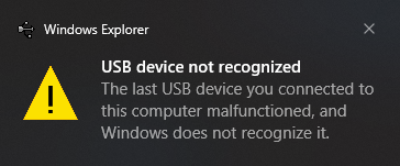
When I arrived, it quickly became apparent that this was more than a glitch. Whenever I plugged the printer into his computer, a message popped up saying: The last USB device you connected to this computer malfunctioned, and Windows does not recognize it.
He didn’t notice this message popping up on the screen because the printer is a fair distance away from the computer, and I guess the message was disappearing before he had a chance to look at it. I tried a different cable I brought along — my cable had the same problem. I also brought my laptop which allowed me to see what would happen in the Linux kernel log when the printer was plugged in:
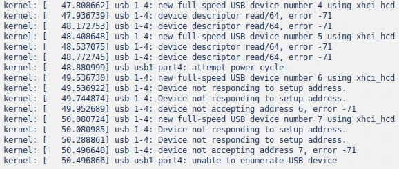
For future web searchers, here are a few of the errors depicted in the image above:
device descriptor read/64, error -71
attempt power cycle
Device not responding to setup address.
device not accepting address 6, error -71
unable to enumerate USB device
Errno 71 is EPROTO according to headers included in the Linux kernel. The kernel documentation says that in the context of USB it usually indicates a a hardware problem such as a bad device or cable. At this point, I was very concerned about my cousin’s ability to print the next day. It wasn’t the cable and it wasn’t his computer. It had to be the printer.
I repeated the same basic troubleshooting steps like powering it off, waiting for a while, and powering it back on, but the USB functionality on this printer appeared to be completely screwed up. He mentioned in passing that someone had recently done some work on his sign outside his office and caused a power blip. It sounded like the start of the printing failure possibly coincided with that event.
We had no choice, so we headed to Walmart and bought a new Brother fax machine/laser printer. It was the last one they had in stock — lucky us! We set it all up and got him all ready for printing the next day. I left the old printer/fax with him for a while just in case something went wrong with the new printer and he needed a way to be able to copy and fax. Don’t worry, that’s not the end of this story!
Once we were confident that he was going to be fine with the new printer, I told him I would try to figure out what was wrong with the USB functionality in the old printer. I hate to see something go to waste. The old printer was still 100% functional as a fax and copy machine, so I was optimistic that the USB circuitry was the only real problem with it. It would be nice for him to have it as a fully-working backup. The old printer actually has some advantages over the new one, too: he likes the phone handset built into the FAX-2840, which is convenient for answering if the fax picks up a voice call on his second line. His new one doesn’t have a handset.
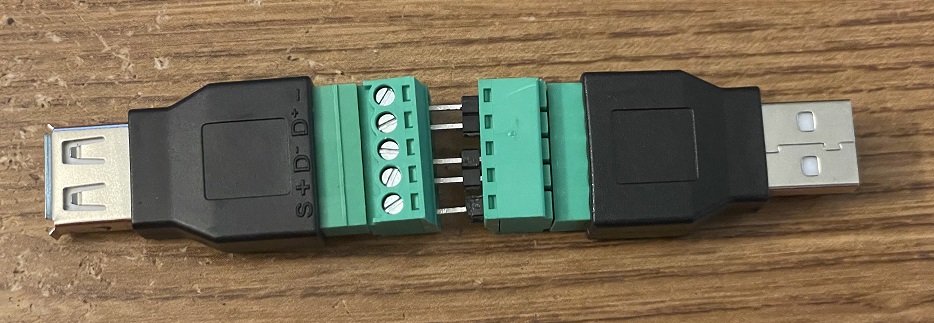
I took the printer home and did some further testing on it. I cobbled together a way to probe the USB data pins on my oscilloscope using a pair of USB-to-green-connector converters and some pin headers.
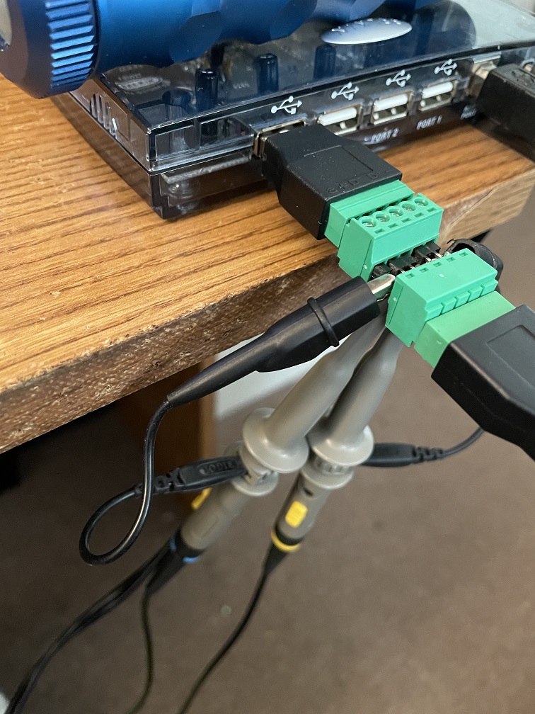
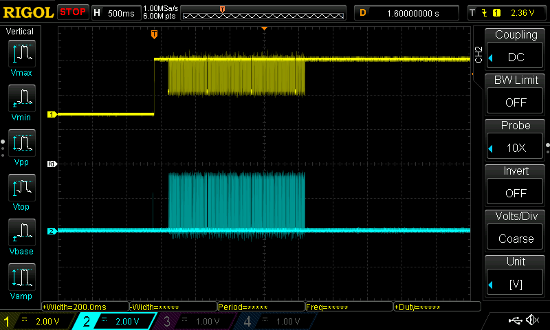
My scope is far too basic to be used for troubleshooting USB high-speed devices, so I inserted a USB 1.1 hub in-line to restrict it to full speed (12 Mbps). I’m definitely not an expert with it, but I was able to pretty quickly notice that something was goofy with the waveform on the D+ pin (yellow in the waveform below). It wasn’t able to be driven down to 0V as soon as the printer was plugged in. It was bottoming out at around 1.2 volts; each little mini-division represents 0.4 volts, and the distance from ground to the bottom of the waveform is about 3 mini-divisions.
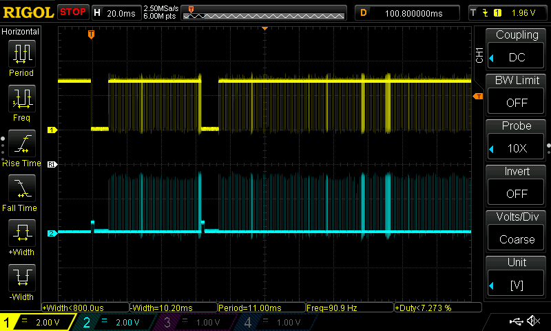
Here’s a closer look after a reset attempt. One thing that’s kind of fun about this picture is you can see the (mostly empty) USB frames every millisecond. Once again, D+ is hanging out at about 1.2 volts when it’s supposed to be at 0. At the very least, it’s definitely interfering with the hub’s attempts to drive it to 0 volts — for example, holding both D+ and D- low for at least 10 milliseconds is how a USB host/hub resets a device.
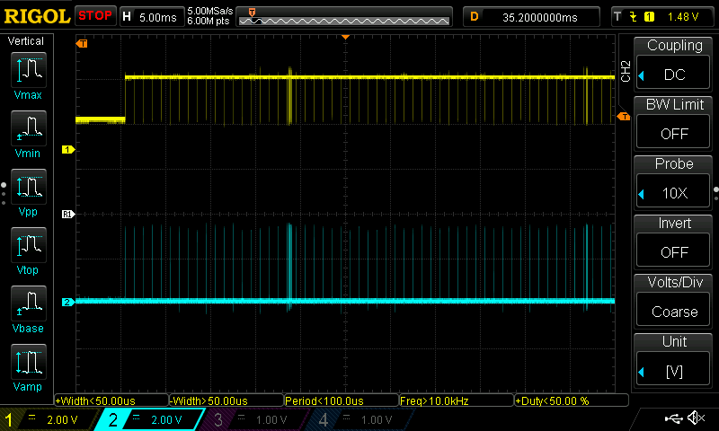
1.2 volts is pretty significant! It’s definitely not low enough to be detected as a low value on the pin. Chapter 7 of the USB 2.0 specification says a low value can be no higher than 0.8V. No wonder it’s not working. Something is trying to communicate, and it looks good on the D- line, but the D+ line is screwed up. For comparison’s sake, here is the same type of oscilloscope trace, but performed using a USB flash drive instead of the printer:
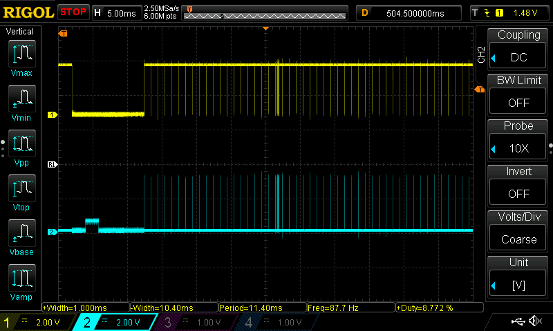
You can see with the flash drive plugged in, D+ is now using the full 0 to 3.3V (or so) range, just like V-. There is also a little 2-millisecond 0.8V blip on D- during reset, which I believe is the “chirp” that the device sends to signify to a compatible host controller that it is a 480 Mbps high-speed device. Since we’re plugged into a USB 1.1 hub, it is ignored and communication continues at 12 Mbps full speed.
This all pretty much just confirmed what I already knew — something hardware-wise was wrong with the printer. Maybe the high-side driver in its USB transceiver was stuck on, so it was fighting against the low-side driver of the computer/hub?
The next step was to disassemble the printer and take a look at the PCB that contains the USB circuitry. Maybe something would be obviously fried, like a protection diode or something? Luckily, the service manual was easy to find with a Google search, and even better, it was super easy to get to the printer’s “Main PCB ASSY”. All I had to do was remove the left side cover, which involved taking out a single screw and unsnapping a bunch of plastic hooks.
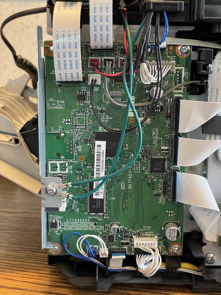
Next, I unplugged a zillion cables, removed 3 screws, and the PCB came right out. One interesting thing to point out about this board is it’s definitely designed with Ethernet in mind; it’s just not populated on this particular model. That’s too bad, because I could have just plugged it into Ethernet instead and avoided this mess. But then I wouldn’t have been able to write a blog post about it!
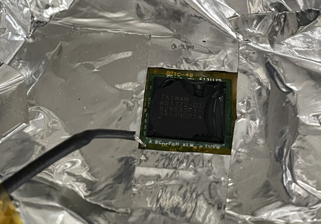
A quick inspection of the USB circuitry on this board revealed that there’s not much to it. The D+ and D- traces go from the port to underneath the A51172-DIANA BGA chip in the center of the board, which is likely the main processor. There are a few resistors involved. I measured them with my multimeter: a couple of 39Ω resistors on D+ and D- (which isn’t a surprise to see on USB lines) as well as a 1.5kΩ resistor on D+. That last resistor is likely the software-controlled pullup that identifies the printer as a full-/high-speed device being plugged in.
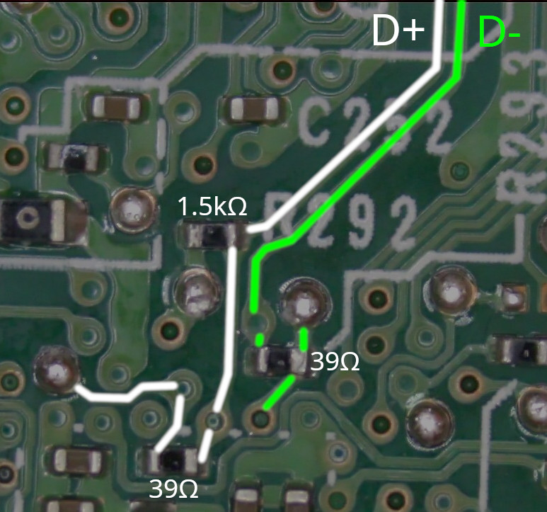
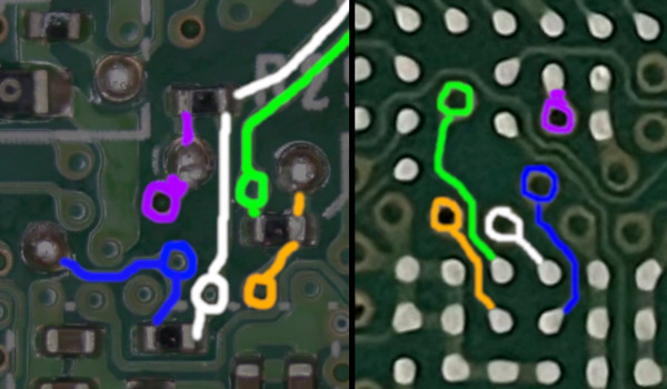
Everything in this section of the board is directly underneath the main processor, so the vias in this section are probably going directly to balls on the chip (or power/GND planes). I noticed there are vias before and after the 39Ω resistors, which implies there are connections to the processor both before and after the resistors. I’m just speculating here because there is no public documentation about the main processor on this board, but it looks similar to this example transceiver circuit from the USB 2.0 specification. The full-speed driver has series resistors (labeled Rs) but the high-speed driver doesn’t. In HS mode, the FS drivers are used to convert Rs into termination resistors — they are driven to 0V which effectively creates ~45Ω termination to ground as the spec requires for HS mode. I’m guessing it’s a similar transceiver design. The resistors are external to the chip and there are separate balls for the HS and FS drivers. I could be totally wrong here; I’m just trying to come up with some kind of educated guess for why there are vias before and after the resistors.
On the top side of the board, there’s also not much going on with the USB circuit. Right near the USB port, I did find three unpopulated diodes D8, D9, and D10 on D+, D-, and 5V respectively. They all go to ground on the other side. These appear to be intended for TVS (transient-voltage-suppression) diodes to help protect against voltage spikes, but Brother didn’t populate them.
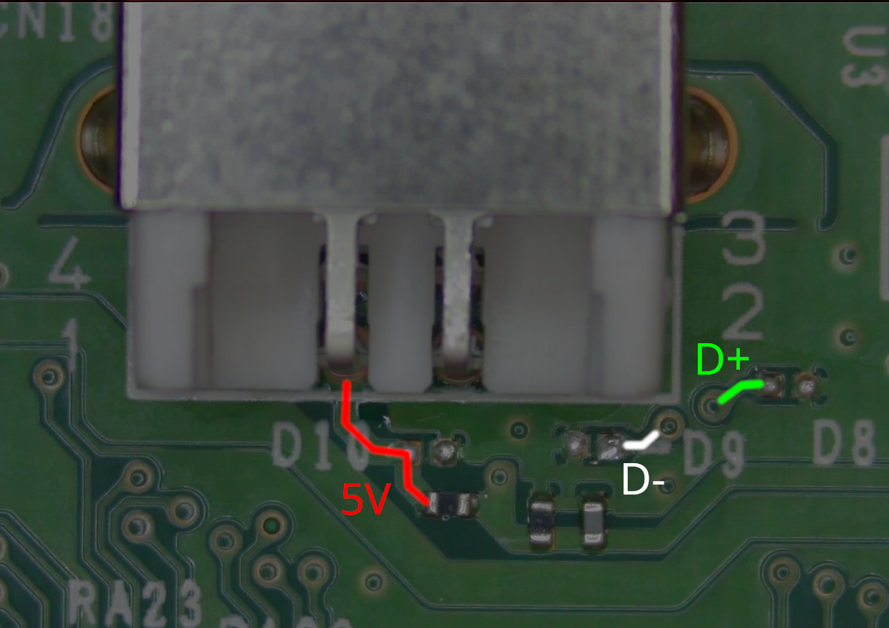
I can’t help but wonder if D8 would have prevented the damage on the D+ line if it had been included. In general, I’ve mostly heard good things about Brother printers. Omitting these protection diodes seems like a pretty poor decision though. It’s an external connector so it should be protected. It seems that any time you plug a USB cable into this printer, you are taking a (small) risk that something bad will happen. Maybe the protection diodes are somewhere else in the circuit, like internal to the main processor or USB connector, so that’s why they omitted them? That seems unlikely, but I’m trying to give Brother the benefit of the doubt. Am I being overly critical here?
Anyway, the simplicity of the circuit left me with only one possible conclusion: there was probably damage inside the A51172-DIANA chip. I searched on AliExpress and found both the chip and the entire board for sale. It didn’t take me very long to weigh my options. I definitely have plenty of soldering experience, but I’m not experienced with BGA soldering and rework. I really wish I could say that I simply replaced the chip, but it wasn’t economical. The whole “formatter board” as it is called on AliExpress was listed for $20.95. The listings for the chip were in the $17 to $23 range. It made more sense to just buy a replacement board, especially taking into account my lack of experience with BGA soldering, not to mention the value of my time. With that in mind, I opted to buy an entire replacement board. Then, I waited and waited and waited for it to arrive from China.
I’m not done with this saga yet though. The service manual pointed out that I needed some Brother service software in order to replace the main PCB. After replacing the main PCB, you’re supposed to rewrite the firmware into it, re-initialize the EEPROM, set the country code, set the serial number, enter a laser adjustment value from a barcode inside the printer, and acquire white level data.
Several of these operations require access to proprietary Brother service software that is only available to authorized service providers: Brusbsn.exe, FILEDG32.EXE, Maintenance_Driver.zip, and LZXXXX_$.upd files containing the latest firmware for the printer. Of course, I didn’t have access to these. I did tons and tons of searching. I did find a super old version of Brusbsn, but it was older than this printer.
I wasn’t about to let the lack of access to Brother’s service utilities get in my way though. I found two nonvolatile memory chips on the board:
- ST 24C32-W: 32-kbit I2C EEPROM
- Macronix MX29GL320E: 4-megabyte flash memory
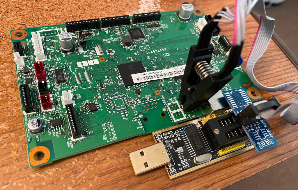
My guess was that the flash chip contained the firmware and the EEPROM contained user and factory settings. I used my trusty CH341A mini programmer and SOIC clip to read the contents of the I2C EEPROM without desoldering it. I’m going to repeat the standard warning I bring up whenever I mention this thing: be careful to verify that the voltages are what you expect. Without a mod to the mini programmer, the data signals will be driven to 5V instead of 3.3V even though it supplies 3.3V for VCC. This EEPROM has a wide range of voltages and is safe at 5V, but it’s on a PCB that appears to be intended for a lower voltage since the Macronix chip is rated for 2.7V to 3.6V, so putting 5V on there could be dangerous.
At first I looked into using flashrom like I’ve used for some of my motherboard shenanigans in the past, but it turns out that flashrom doesn’t support I2C EEPROMs. I did some more searching and discovered ch341eeprom. Here’s the command I used to read the chip contents:
./ch341eeprom -v -s 24c32 -r readback.bin
I read it back a few times and made sure each readback was identical to verify I got a good dump. Inside the dump I spotted the serial number of the printer and the name of my cousin’s business. Those were both pretty good signs that I was correct about what’s stored on the EEPROM, but I still wasn’t 100% sure. I could use my CH341A programmer to program this EEPROM dump to the new board, but what if the EEPROM format was different between firmware versions and the new board came with a different firmware version?
If there was any conflict like that, I could swap the Macronix flash chip from the old board to the new board in order to ensure that everything was 100% identical, but I thought it would be easier to just try the new board with the bad board’s EEPROM contents and see if that would be sufficient. I didn’t want to mess with soldering if I didn’t need to.
When the new board arrived, I dumped its EEPROM just in case, and then overwrote it with the content of the damaged board’s EEPROM:
./ch341eeprom -v -s 24c32 -w readback.bin
I also verified it a few times to make sure it wrote successfully:
./ch341eeprom -v -s 24c32 -V readback.bin
I installed the new board in the printer, powered it on, and success! It turned on with no problems. I went into maintenance mode and did a printout of maintenance information. First of all the printout worked properly and looked great, which was an excellent sign. Everything matched the previous maintenance printout (from before I swapped boards) except for the firmware version and page count. The new board came with firmware version F, whereas my cousin’s printer had firmware version J. But that difference didn’t seem to matter.
It came down to the final moment of truth. I plugged it into my computer. I was a little scared at first because a printer wasn’t detected automatically, but it was simply because I had to download and install the driver. I was expecting Windows to handle it all for me, but I guess Brother’s drivers for this printer aren’t in Windows Update for some reason. After the driver was installed, it worked perfectly. The bottom line is that replacing the main board completely fixed the printer, and copying the old EEPROM contents over preserved the settings and factory info such as the serial number. Who needs Brother’s service utility when you can just use your EEPROM programmer instead?
Interestingly, I ran Brother’s firmware updater which brought the firmware up to version G, and now it tells me there are no updates available. That’s still older than the original version J. Oh well — it seems to work just fine, so it’s not worth bothering to swap the flash chips to restore its original newer firmware version.
Here’s what the printer’s USB signals look like on the scope when I plug it in now. You can see that low values on D+ correctly go down to 0V, and the high-speed chirp also shows up on D- whenever both D+ and D- are low (reset condition).
By the way, the new board was also missing the TVS diodes. What the heck, Brother? I bought some TVS diodes in 0402 form factor based on TI’s recommendations:
- ESD321 (for D+ and D-)
- TPD1E10B06 (for +5V)
I practiced on the old board and came to the realization that I’m not skilled enough to install them. I’ve done 0402 stuff in the past, but never crowded right up against a USB port with pads not designed for hand soldering. One of the pads for each diode being connected to a beefy ground plane doesn’t help, and components this small are really fragile too. The microscope view makes it look a lot easier than it actually is. I wish I had been able to install them on the new board, but it was too much of a struggle during my practice run and I didn’t want to risk screwing up the newly repaired printer. I probably could have temporarily removed the USB jack to get the job done, but I really just wanted to get it back to my cousin in working condition. Also, I was worried in the back of my mind that maybe Brother omitted them for a technical reason (not involving cost), but that seems doubtful.
Even though it made no sense at all from a monetary (let alone sanity) standpoint, I also ordered a replacement A51172-DIANA chip on AliExpress to see if I could have simply replaced it myself. Just for fun!
This led me to really appreciate my decision to replace the whole PCB. The process of removing the old chip with my preheater, hot air station, and 18mm x 18mm BGA nozzle went fine, but I messed up when soldering the new chip on. I used too much air flow which caused the chip to move out of position. I gently nudged it (which caused it to pull itself back into place), but I think the damage was already done at that point. After I was finished, the new chip also seemed to be much closer/flatter to the PCB than the original chip was; I’m thinking the pads were covered with solder paste when the board was originally soldered. I’m curious if that would have made a difference.
Although my BGA soldering attempt was a failure, it was cool to be able to confirm what I concluded earlier about the USB signals before and after the resistors going to different balls on the chip:
Overall, this was still a success and a great learning experience. Maybe it will give me an opportunity to practice BGA reballing as a challenge to see if I can revive the bad board. There are unpopulated debug power and UART headers, so I can definitely do some testing without the actual printer.
I hope this helps someone out there who might need to repair a Brother printer in the future. At least with this model, you can bypass the difficult-to-find service software by using an EEPROM programmer instead. It would be nice if manufacturers weren’t so secretive about this stuff!


Thanks for this post- it was interesting seeing someone actually fix a broken printer like this.
Thanks Steve! It was a lot of fun. I’m still holding out hope that I might be able to reball the replacement BGA chip and fix the original board, but at this point it’s all just for fun.
[…] Doug Brown ☛ Diagnosing and repairing a Brother fax/printer USB failure […]
[…] Doug Brown ☛ Diagnosing and repairing a Brother fax/printer USB failure […]
[…] Read the lengths to which this printer was handled in the blog post here. […]
Update: I noticed that the old board is warped a bit. I’m guessing I did that during my chip removal/resoldering attempt. I have a lot to learn about BGA rework.
Even with the new knowledge that the board is probably screwed up now, I removed the new chip from the bad board, reballed it, and soldered it back on. The board still doesn’t work, but it was definitely quite a learning experience!
Brother’s approach to this repair is NOT exactly friendly. Most printers have the ability to reconfigure the NVRAM parameters (serial number, page counts, etc.) from the service menu on the printer itself. Replacement boards usually come with firmware pre-installed too.