What follows is the story of how I fixed not one, but two, different flawed Altera USB Blaster clone devices that never worked correctly after I bought them.
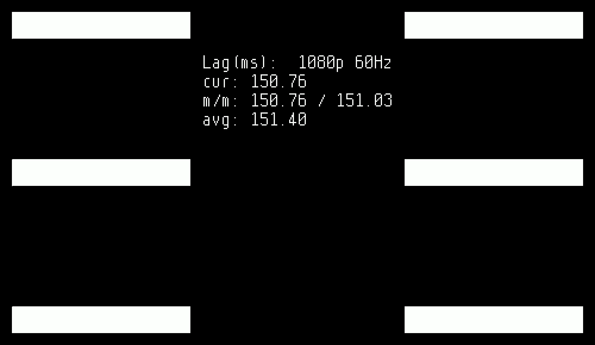
I recently built a few Time Sleuths for HDMI input lag testing. Time Sleuth is a neat little open-source project that allows you to measure the time it takes for your TV or monitor to display an image. The way it works is an Altera/Intel MAX 10 FPGA creates a video signal that is mostly a black screen with some blinking white boxes. It feeds the image off to a TI TFP410 DVI transmitter, and also looks for a pulse on a photodetector. It measures the difference in time between when the white box blinked on and the photodetector saw it, and displays it as a number on its generated video signal with some min/max/average stats. Pretty cool! If you’re not into soldering, you can also buy them fully assembled.
Anyway, after soldering up a board, I had to flash a bitstream to the Altera FPGA. I immediately discovered that the official Altera/Intel USB Blaster JTAG cable costs $300. I wasn’t willing to fork up that much money for a programmer I would potentially never use again, and I noticed that there are a lot of cheap clones out there, so I did some research and decided on a clone to buy.
I read many good things about the Terasic USB Blaster, but I thought that $69 was still a little on the high side for pricing, so I went for something even cheaper. In hindsight, I was completely wrong. $69 is very reasonable for a reputable product. The Terasic programmer would have been the best choice and would have avoided the mess I’m about to describe, so keep that in mind if you’re reading this and trying to decide on a programming cable to buy.
I opted for the Waveshare USB Blaster V2. Waveshare’s site seemed pretty nice, and I saw at least one pretty good recommendation of it on Reddit. I did notice an Amazon review that said it works intermittently in Linux, but I bought it despite the warning. Worst case, I could use Windows instead.
Well, it turns out that one-star review was spot on. I would even say that it was overly optimistic when describing the Linux compatibility. I couldn’t get the freaking thing to ever program an FPGA correctly at all in Linux, at least with Quartus Programmer or the related command line tools. It would fail during random parts of the programming process. Erases actually did work sometimes, but the longer the operation it was being asked to perform, the more likely it would fail. It was scary because I was starting to think I had made a mistake when building my first Time Sleuth, but then I fired up my Windows 10 VM and it programmed perfectly on the first try. I’ve confirmed that it always works fine in Windows.
I will say that I was able to get it to work with OpenOCD and UrJTAG by playing back an SVF file, but it was really slow and it felt clunky. I wanted something compatible with Quartus Programmer! I asked Waveshare about getting it to work in Linux, and this is what they said two days later:
I’m sorry that we did not test it with the Linux PC, it should have compatibility problem.
It is recommended to use in Windows PC.
At this point, I cracked it open to take a look. It’s actually pretty nice.
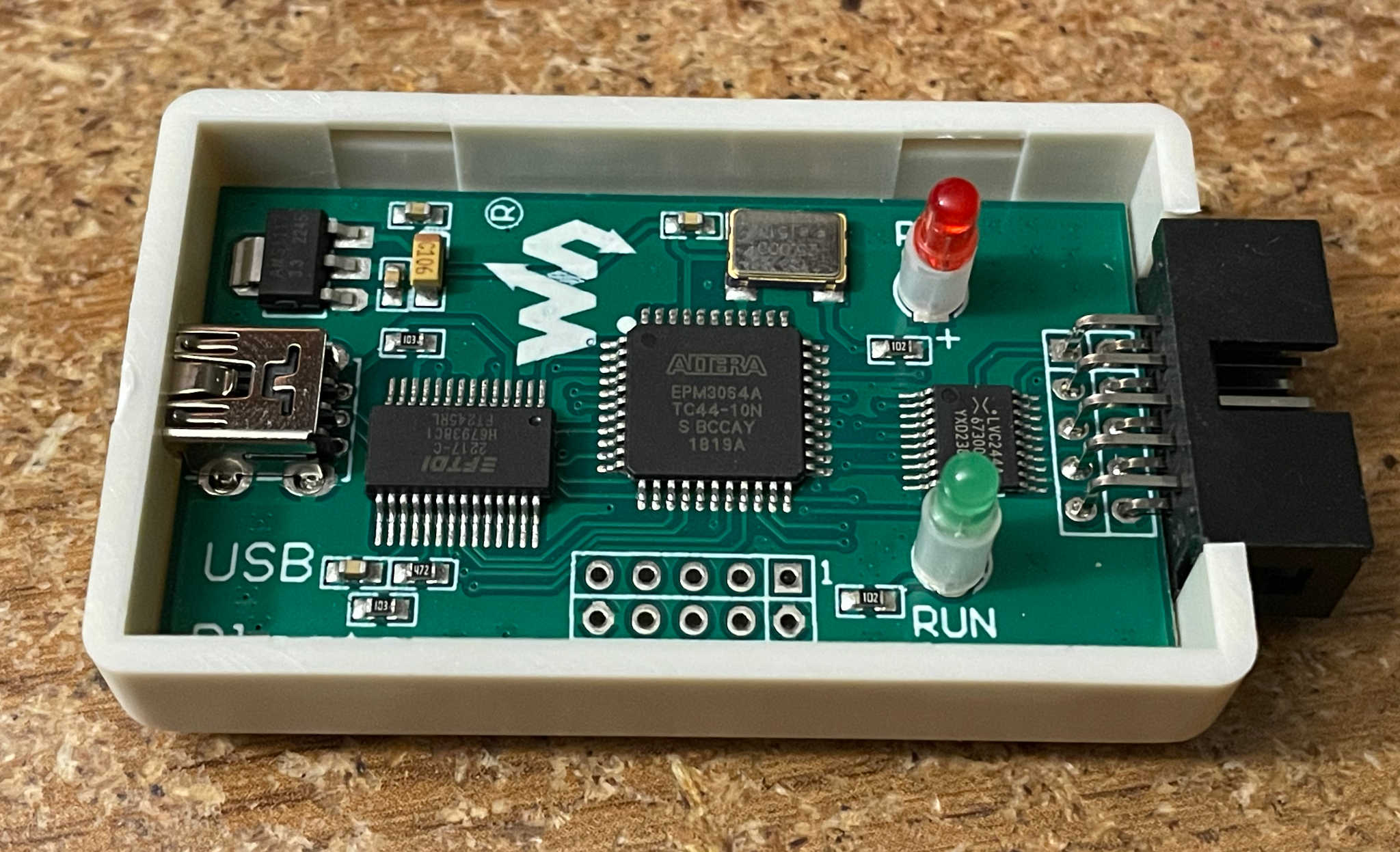
It uses an FTDI FT245RL and an Altera EPM3064A CPLD, as well as a Nexperia 74LVC244A buffer. I have often seen people say that the FTDI + CPLD USB Blaster clones are typically higher quality than the really cheap clone devices out there. That’s because Altera’s actual USB Blaster (version 1, anyway) uses a similar setup internally. I’m not sure if it’s quite as nice as Altera’s design, but I like seeing the 74LVC244A buffer in there. As far as I can tell, it’s being used as a level shifter to ensure compatibility with different voltages, which is how Waveshare is able to say it supports 1.2V to 5V programming voltages. I’m not convinced that 5V programming voltage would actually be in spec with the 74LVC244A’s recommended supply voltage range of 1.2V to 3.6V, but I digress.
Why would a device like this work correctly in Windows but not Linux? The Altera software looked pretty similar between Windows and Linux. I’d be shocked if they weren’t using the same codebase underneath. This seemed like the perfect thing for me to investigate, especially since I have a hardware USB sniffer. I looked at the raw USB traffic, although a hardware sniffer ended up being overkill for this. The traffic actually looked quite a bit different between Windows and Linux. I guess the Windows software assembles the JTAG commands slightly differently, and something about the way Windows does it works better with this device.
To limit the scope of what I was looking at, I decided to focus solely on Linux. Since I could get Linux to both succeed and fail during a short procedure like erasing the chip, I used Wireshark to do a usbmon capture of good and bad erases. Then I studied the captures in depth.
First, I needed to understand how the USB Blaster works. I also didn’t know much about JTAG, so I read up on it. The USB Blaster’s protocol is actually very simple. As a brief summary of the linked info, the host computer sends a bunch of bytes to the device. If the highest bit in a transmitted byte is 0, the rest of the bits contain raw state to put directly on the various JTAG pins, as well as controlling the status LED. If the highest bit is 1 instead, then the bottom 6 bits contain a length, and then there are that many bytes following that contain 8 bits that will be consecutively shifted out through TDI/TCK. So basically the byte mode is an optimized way to send data faster if you are aren’t needing to twiddle the other pins like TMS.
Bit 6 is used in both modes to tell the USB Blaster to also read data from the TDO pin and send it back to the computer. The USB Blaster sends out heartbeat packets every millisecond or so even if there’s no data that has been read since last time. The packets appear to always be prefixed with two bytes: 0x31 and 0x60. I’ve noticed that the Waveshare device sometimes sends “0x31 0x00” as the prefix instead, but I don’t think it matters.
Next, I read up on the linked JTAG documentation above. It explains how it’s a state machine and the TMS pin is used to decide how to jump around between the different states each time a TCK cycle occurs. It also provides some useful examples of how you can figure out what devices (if any) are present on the JTAG chain. I manually decoded the JTAG operations in the Wireshark USB captures. Here’s an example of a recorded packet sent to the Blaster:
0000   7e 7f 7e 7f 7e 7f 7e 7f 7e 7f 7e 7f 7c 7d 7e 7f
0010   7c d0 ff 03 b3 3f fc ff ff ff ff ff ff ff ff ff
0020   ff ff 7c 7d 7c 7d 7c 7c 7c 7c 7c 7c 7c 7c 7c 7c
0030   7c 7c 7c 7c 7c 7c 7c 7c 7c 7c 7c 7c 7c 7c 7c
And here’s the response that I got back from it:
0000   31 60 03 03 03 03 03 03 03 03 03 03 03 03 03 03
0010   03 03 03 77 43 60 0c fc 03 b3 3f fc ff ff ff ff
0020   ff ff ff 03 03 03 03 03 03 03 03 03 03 03 03 03
0030   03 03 03 03 03 03 03 03 03 03 03 03 03 03 03 03
You’ll notice that the response has one more byte than the transmission. Actually, it has one fewer byte, because the “31 60” prefix doesn’t count. The reason it has one fewer byte is because the transmitted “D0” byte has bit 7 set, so it’s indicating we’re going into byte mode for 16 bytes (the lower 6 bits are 0x10 = 16). That byte doesn’t actually perform any operation itself, so it doesn’t cause a response byte to be sent. But because bit 6 is set in it, all 16 bytes transmitted will have associated responses. They show up as the “77 43 60 … ff ff ff” in the response.
Going into the actual nitty-gritty detail of this transmission is well beyond the scope of this post, but what’s happening here is the Altera software is reading the IDCODE of the attached chip(s). It’s very hard to see in the hex dump because the bits aren’t on perfect byte boundaries, but the Altera CPLD responds with a chip ID of 0x031810DD, which is exactly what the 10M02SCE144 is supposed to respond with.
I kept following along in the USB/JTAG trace and eventually found a point where the data readback differed between the success and failure captures. The Altera software appeared to be attempting to enter the Shift-IR state, but the readback we got didn’t make sense after entering that state.
At this point I had no choice but to blame something in the adapter. It was returning different results when given the exact same input both times. It was random. It kind of seemed like it was probably something related to timing, like maybe it was right on the boundary of being out of spec on setup/hold times or something.
Here’s what the traffic looked like on an oscilloscope. In particular, this is what the optimized byte mode traffic looked like (TCK):
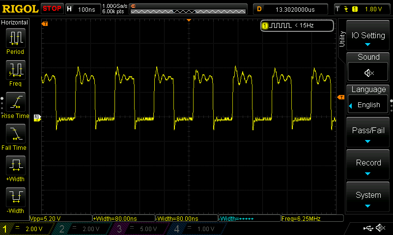
I did notice something a little funky with this. The pulses are 6.25 MHz. This makes sense because the oscillator is 25 MHz, so it’s being divided by 4. My understanding is designs like this, including the original USB Blaster, typically have a 6 MHz JTAG clock though. I began wondering if it’s slightly overclocked. I think that would explain intermittent behavior. I even found an old discussion from 2006 where “kawk”, who designed a CPLD bitstream for this setup, ran their design slightly overclocked at 25 MHz and it worked okay, but other people reported problems and had to slow it down.
This gave me an idea. The FTDI chip has its own internal oscillator, so I was totally free to mess around with the frequency that the CPLD was running at without interfering with any of the USB circuitry. I didn’t have any oscillators sitting around, but I did have an RPi Pico I could use. I wrote a simple program in MicroPython to set up GP0 as a 24 MHz clock signal with 50% duty cycle:
from machine import Pin, PWM
pwm = PWM(Pin(0))
pwm.freq(24000000)
pwm.duty_u16(32768)
Then I removed the 25 MHz oscillator from the Waveshare Blaster and soldered a wire to the Pico’s GP0 instead (and another for ground).
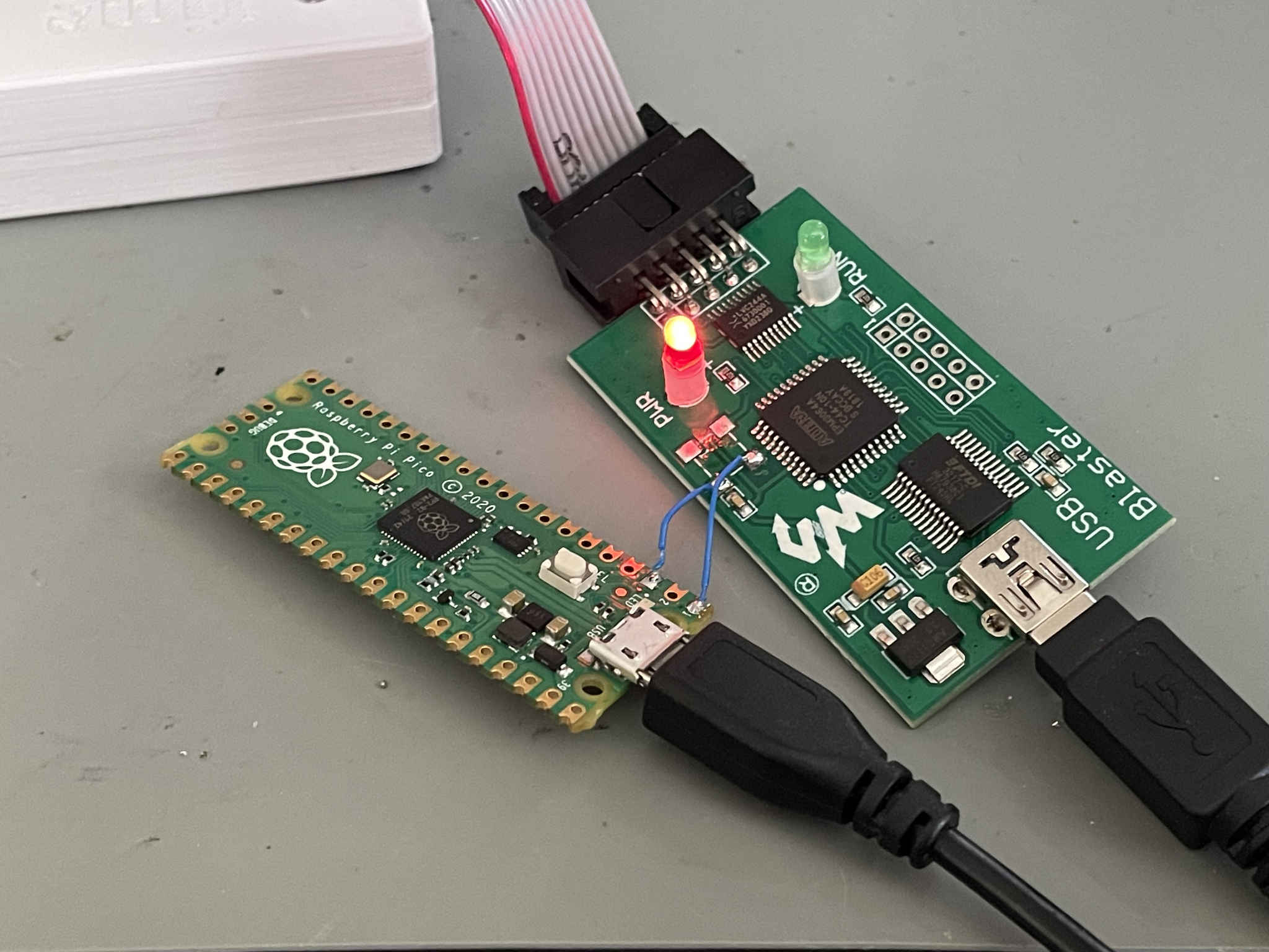
When I verified the frequency with my multimeter, I discovered that the RP2040 was outputting a 25 MHz signal even though I had asked for 24 MHz. I quickly realized this is because the Pico is clocked at 125 MHz by default and the PWM frequencies would have to be an integer divisor of that. I probably could have changed the Pico’s frequency with machine.freq(), but it was easier to just keep stepping up the divider instead. (125/6) = 20.83 MHz, which is well below 24 MHz.
Running at 20.83 MHz, it still seemed erratic. So I bumped the clock speed down even more to (125/7) = 17.86 MHz. At this rate, it mostly worked! I did see it fail a few times though, so I figured I was getting closer to reliability. The next lowest possible frequency of (125/8) = 15.625 MHz seemed to be the sweet spot. It worked perfectly every time with that slower clock speed. Success!
I’m still waiting for a few random oscillators to arrive from Digi-Key so I can close this one out for good. I ordered them before I thought to try using an RP2040 as a stand-in, so the speeds I ordered were 24 MHz, 20 MHz, and 12 MHz. I wish I would have ordered a 15 or 16 MHz one as well. I’m feeling pretty confident that soldering in the 12 MHz one will solve everything and the Waveshare USB Blaster will work perfectly in Linux after that. Sure, it’ll slow everything down quite a bit, but at least it’ll be reliable.
I’m still kind of mystified that the problem never happens in Windows. I’m guessing the CPLD design has a subtle timing bug that the Windows version of Altera/Intel’s software doesn’t hit because it arranges the JTAG traffic in the USB packets completely differently.
Normally this would be the end of this type of blog post, but you may have noticed at the top that I mentioned I fixed two different USB Blaster clones. Buckle up, because we’re just getting started. After the Waveshare one didn’t work, and before I figured out what was really going on, I bought an even cheaper one on Amazon for $9.
I didn’t feel very optimistic about this based on the reviews. There were a lot of reviews that said it didn’t work at all. Several reviewers said it bluescreened their Windows computers. Despite those reviews, and given how much time I had invested into this problem, I thought it would be fun to see what was wrong with this cheapo clone. Am I crazy or something?
It arrived yesterday afternoon. I plugged it into my Linux machine and tried it out. Of course, it didn’t work. No surprises there. It showed up with the correct device ID and the software correctly recognized it, but Quartus Programmer didn’t like it at all.
usb 3-2: New USB device found, idVendor=09fb, idProduct=6001, bcdDevice= 4.00
usb 3-2: New USB device strings: Mfr=1, Product=2, SerialNumber=3
usb 3-2: Product: USB-Blaster
usb 3-2: Manufacturer: Altera
usb 3-2: SerialNumber: FFFFFFFF
As far as I could tell based on a quick Wireshark USB capture, the traffic looked normal except for one thing. It wasn’t responding with any data. There were no response packets at all, not even the periodic idle “31 60” packets that should have been showing up.
Then I tried it in Windows and immediately replicated the BSOD problem that other reviewers had mentioned. It quickly gave me a blue screen with the bug check being PFN_LIST_CORRUPT. I didn’t even have enough time to open the Quartus Programmer software. Some quick Googling revealed that I wasn’t the only one experiencing this problem with cheap Altera USB Blaster clones. Other people had solutions that often involved trying custom Windows drivers, but I didn’t really want to mess with that. I didn’t really care about Windows support anyway. It didn’t work in Linux and that was all that mattered to me.
So yeah, this clone seemed totally useless, just like most of the reviews had said. It’s interesting, because I’ve also seen a lot of people online say that the cheapo clones work great. I guess there must be different versions out there and some of them work better than others. I decided to open this one up and see what it looked like inside:
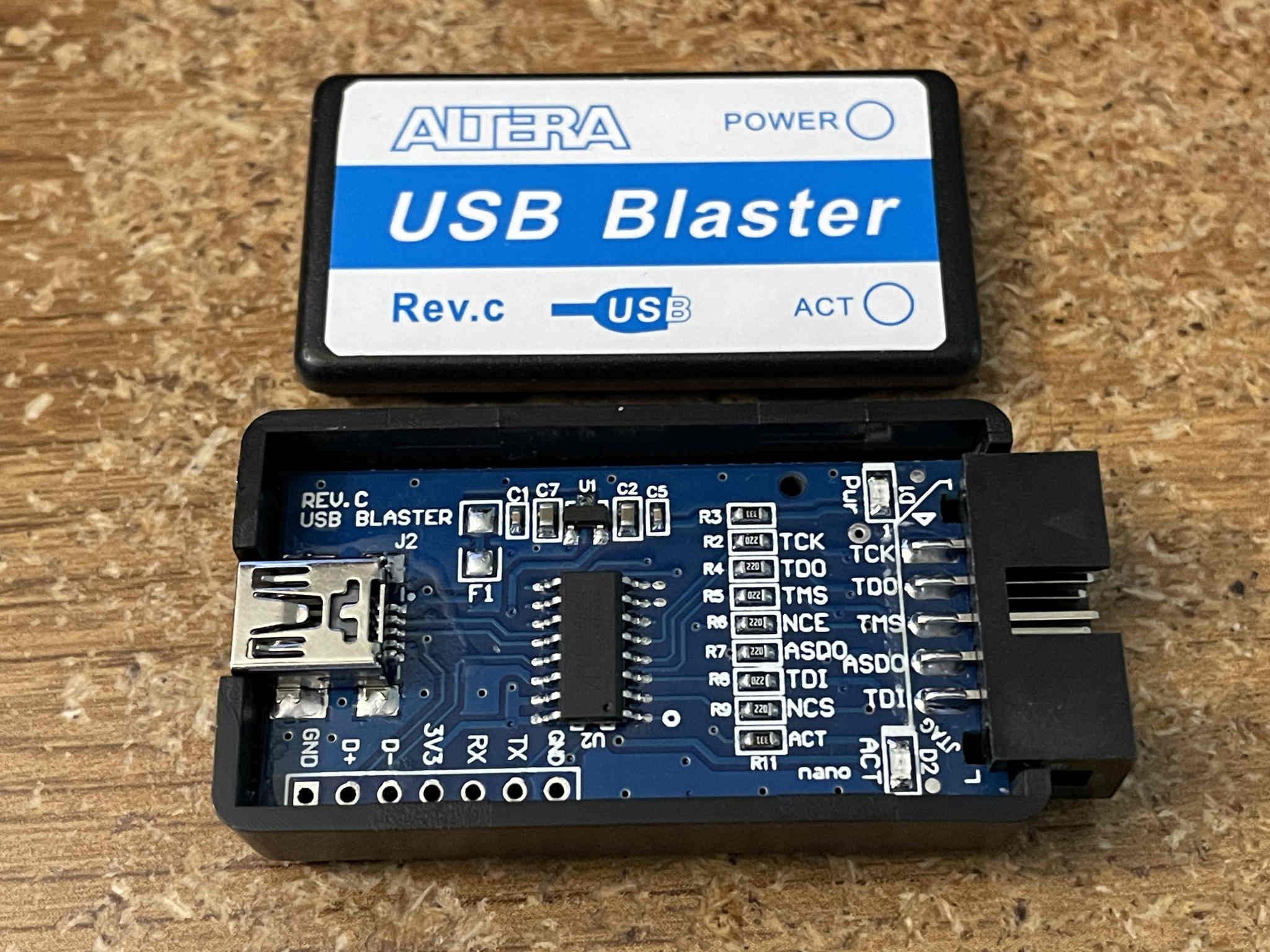
There is only a single chip, which isn’t identifiable in the picture. It’s a WCH CH552G microcontroller. This is one of those extremely inexpensive microcontrollers that was making its rounds on the Internet a few years ago. It’s an 8-bit 8051 MCU that has a fair amount of neat little features. It has crystal-less USB support, for example. As of this writing, LCSC has a few in stock for $0.62 each. Not bad for the capabilities it has. However, I think this board design is very basic and is a great example of how you get what you pay for. As far as I can tell, it’s hardwired for 3.3V operation. There are series resistors on each pin, so I don’t know if that helps with avoiding damage if you hook up a lower-voltage device or what.
I searched around to see if anyone else had encountered these chips in USB Blaster clones. I saw that many of the other cheap clones have STM32 or PIC microcontrollers. I guess the market has been flooded with different versions. Some of the people who say theirs work great must have gotten a different model, or at least different firmware on it.
I found a few mentions of the CH552G being used in these. One interesting thing was a Hackaday post from a couple of months ago where someone else had developed one (closed source), as well as another project from 5 years ago with open-source firmware, based on top of Blinkinlabs’ CH55x SDCC SDK port.
This seemed right up my alley! A new idea/challenge sprung to mind. Could I get the open-source firmware from 5 years ago compiled and working on this non-functional CH552G USB Blaster clone I just bought? Would it work properly in Linux and avoid the Windows blue screen of death? The Time Sleuth runs at 3.3V so it would be completely safe to try out.
Of course I couldn’t resist taking on such a challenge. So last night, I started on it. What better way to spend a Friday night? The first task was to determine the pin mappings using continuity mode on my multimeter. The board is so simple and the MCU is so small that it didn’t take long before I had the entire pinout I needed:
- Pin 1 – P3.2 – TMS
- Pin 2 – P1.4 – NCS
- Pin 3 – P1.5 – TDI
- Pin 4 – P1.6 – TDO
- Pin 5 – P1.7 – TCK
- Pin 6 – ?
- Pin 7 – ?
- Pin 8 – ?
- Pin 9 – P1.1 – ACTIVITY LED (ACT)
- Pin 10 – P3.3 – ASDO
- Pin 11 – P3.4 – NCE
- Pin 12 – USB D+
- Pin 13 – USB D-
- Pin 14 – GND
- Pin 15 – VCC
- Pin 16 – V33
Next, I got the CH55x SDK up and running. The documentation on the SDK’s GitHub project was excellent. It didn’t take long before I was ready to try out a program to blink the activity LED on and off. I simply modified the “blink” example to use P1.1 instead of P1.7 and built it.
There are so many awesome tutorials out there about how to work with these chips, so it wasn’t really a problem to figure out how to program it. I installed ch55xtool. These chips are cool because they have a USB bootloader that puts it into a programming mode if you hold a pin high at startup. You don’t need a special programmer or anything. The datasheet says that you need to be running at 5V to flash them, but I’ve found so far that flashing works fine at 3.3V too. They do say you only get about 200 flash cycles per chip, so you can’t go crazy with reflash attempts. Oh well, they’re so inexpensive that it doesn’t matter that much.
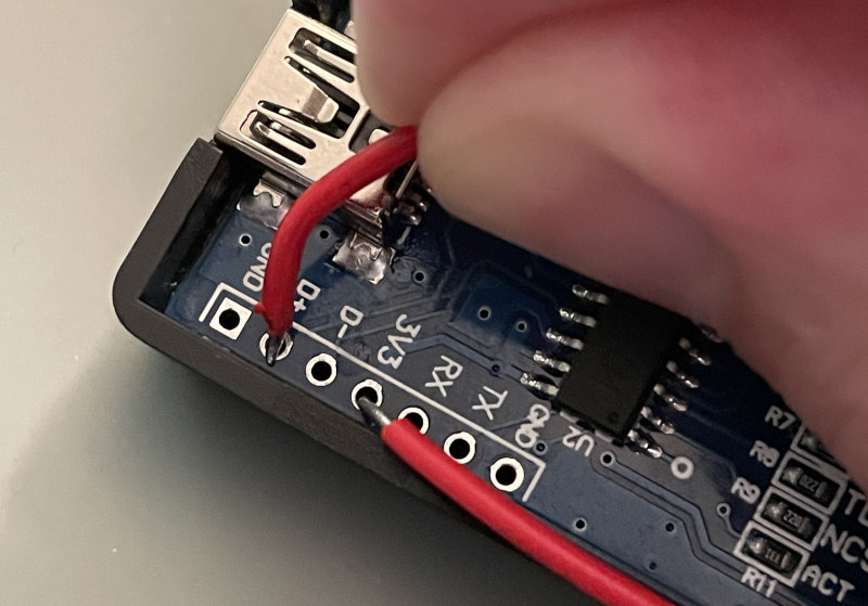
To force it into the bootloader, I just held a wire between the 3V3 and D+ pins which were conveniently located on a header, plugged it in, and then quickly removed the wire to avoid shorting it for too long and also to allow USB communication to commence. A resistor would probably be safer.
Then it showed up as a different USB device in Linux, so I knew I had done something right:
usb 3-1: new full-speed USB device number 69 using xhci_hcd
usb 3-1: New USB device found, idVendor=4348, idProduct=55e0, bcdDevice= 2.50
usb 3-1: New USB device strings: Mfr=0, Product=0, SerialNumber=0
I briefly contemplated something in my head at this point: there was no going back as soon as I went any further. I’d erase the stock firmware on this device and my only hope would be to get this open-source firmware working. I didn’t care though. The device was useless with its original firmware so I had nothing to lose. Here’s the command I ran to flash the chip:
ch55xtool -v -f blink.bin
The flash was successful, but my blink test firmware didn’t freaking work! Nothing happened on the LED. I checked the other pins and there was no sign of life. I was pretty irritated. I really thought I had done my homework on this. I tried some other flashing utilities — even the vendor’s WCHISPTool in Windows. Nothing worked. I tried resetting all the config settings on the chip to default just in case one of the settings was screwed up, but nothing seemed to fix it. I started to worry that I had done all that reverse engineering work for nothing.
When I came to my senses after an hour or so, I realized I should start tinkering further with the sample code to see why it was failing. I noticed a call to CfgFsys() at the start of main(). I tried commenting it out, and all of a sudden the LED started blinking! (At the wrong rate, but that’s okay). Further reading in the datasheet revealed the problem as soon as I realized that CfgFsys() was writing to the CLOCK_CFG register. The SDK was defaulting to a FREQ_SYS of 24 MHz in examples/Makefile.include, but when the chip is running at 3.3V, it can only do a maximum of 16 MHz. I simply had to override FREQ_SYS to 16000000 or lower in my Makefile. Once I did that, the blinking LED demo worked and I was all set!
The next order of business was to get the open-source CH55x-USB-Blaster firmware compiling. The easiest thing to do was to drop it into the examples folder of the SDK as another example project. It was even including ../Makefile.include in its own Makefile, so I think that’s the CH55x-USB-Blaster developer’s intended way of integrating it. I added the FREQ_SYS override to its Makefile. I also modified the pin mappings. They were mostly correct, but I had to strip out a bootloader entry button and move a couple of pins around. I also noticed the code was sending a prefix of “01 60” instead of “03 60” on transmitted packets so I went ahead and changed that to match the original USB Blaster.
After I did that, I tried plugging it in…and nothing. Well, almost nothing. My computer detected a device plugged in, but nothing happened after that. In Wireshark it looked like a request for the device descriptor was being sent out, but nothing was happening in response.
usb 3-1: new full-speed USB device number 88 using xhci_hcd
Looking at the USB IRQ handler in the code, I was suspicious about the way the start-of-frame (SOF) interrupt was being handled. It didn’t look like the SOF interrupt was being cleared properly. I just disabled the SOF interrupt altogether for testing. It didn’t seem super important; it was just incrementing a counter which was later used to decide to send out an idle “03 60” packet every so often.
As soon as I disabled it, my reflashed USB Blaster clone sprang to life!
usb 3-1: new full-speed USB device number 92 using xhci_hcd
usb 3-1: New USB device found, idVendor=09fb, idProduct=6001, bcdDevice= 4.00
usb 3-1: New USB device strings: Mfr=1, Product=2, SerialNumber=3
usb 3-1: Product: USB-Blaster
usb 3-1: Manufacturer: Altera
usb 3-1: SerialNumber: C0BFA6D7
Amazingly enough, in this state, it worked completely fine in Linux. I had successfully fixed my $9 junk cheap USB Blaster to actually work correctly for flashing my Time Sleuth! I was totally stoked!
Then I plugged it into Windows to see if I had fixed the Windows compatibility, and it bluescreened right away. It was the exact same PFN_LIST_CORRUPT error as before.
What in the world? But it worked in Linux now! Why would Windows be upset?
I think what’s going on here is if your device pretends to be an FTDI chip, but it doesn’t perfectly emulate it, weird stuff happens when the official FTDI driver doesn’t see something it’s expecting. I’ll leave it to you as the reader to decide whether that’s accidental or intentional on FTDI’s part. Whether it’s accidental or not, I think it’s pretty bad that the driver can crash the system if the device doesn’t respond correctly. Anyway, I remembered that I had disabled the SOF interrupt that was part of the logic for how often to send out the empty “03 60” packets. I looked through some other code examples of how similar USB controllers handled SOF interrupts and tweaked the firmware accordingly.
With this change implemented, the SOF interrupt seems to work as intended now. I’m noticing periodic empty “03 60” packets when the programmer is in use now when I sniff the traffic in Linux, and Windows no longer crashes when it’s plugged in. I am successfully able to flash my Time Sleuths from Quartus Programmer in Linux and Windows with no problems.
After I got it fully working, I realized the activity LED was backwards. It was on most of the time and off when it was busy. I just had to invert the LED in the code. It was a quick fix. The only other weird thing I’ve noticed is that the Time Sleuth backfeeds power into the cheap USB Blaster, so I just try to plug them both into power at about the same time to be safe. I don’t think there’s anything I can do in software to fix that.
Here’s my GitHub fork of the CH55x-USB-Blaster firmware, along with a release binary you can flash to your device if you’ve somehow made the same mistake I did and bought a completely useless USB Blaster clone. Just keep in mind a few things: the circuit is very basic and only appears to be designed for 3.3V programming. This will only work if yours has the same pinout as mine. I take no responsibility if you brick your useless USB Blaster by trying this firmware out. I’ll take lots of credit if it fixes it though! Credit also goes to VladimirDuan on GitHub for the original implementation of the CH55x USB Blaster firmware, as well as Blinkinlabs for the excellent SDK port. Not to mention the developers of SDCC! It’s awesome seeing so many open-source projects help breathe a solution like this to life.
Not too bad for a night’s work, huh? I converted a $9 piece of Amazon garbage into a functional USB Blaster clone in just a few hours. I’m pretty happy with myself! I don’t want to toot my own horn too much, but it seems kind of ridiculous that these junk devices are being sold totally nonfunctional, yet it only took me one evening to piece together some open-source firmware to fix it. Do they even test these things?
I’m also satisfied with my research into the first device I looked at, the Waveshare USB Blaster. I’m pretty sure as soon as I have a slower oscillator to solder in, it will also begin working perfectly, albeit slower than it potentially could be. It would really be cool to figure out how to make a new bitstream to load into it that could operate at the full 25 MHz original clock rate. I would probably need a bit of help on such a project though.
I hope this info is useful to someone out there!


One thing I should point out is that after doing further testing, it looks like newer versions of Altera/Intel’s programming software don’t work with either of the clone devices I fixed in this post.
Version 18.1 works great with both devices. 24.1 works okay for auto detecting and erasing, but it gets stuck early during the flash writing process when the progress is at about 4%. This is repeatable on both Linux and Windows.
If 24.1’s jtagserver.exe/jtagd is running, I can still use the 18.1 software and it succeeds. So it’s not the JTAG server itself that is the problem. I might investigate further if I have some time. It might be possible to fix this compatibility problem in the cheapo clone’s firmware if I can determine what’s going on.
Further testing reveals that 20.1.1 is the last version that works correctly for me on both Linux and Windows with both of these inexpensive USB Blasters, at least in combination with the MAX 10 FPGA I’m playing with. Intel says the last supported version for MAX 10 is 21.1, but 21.1 has the “stuck at 4% progress” problem for me. I guess it’s possible that this is a device support issue in the Quartus software rather than an incompatibility with the cheap clones. I’d have to try programming a newer FPGA, or buy a more expensive legitimate USB Blaster, to know for sure.
Awesome write up! Fun, inspiring, and educational!
Thank you Justin! It was a lot of fun while I was tinkering with it too!
Update: To the surprise of nobody at all, soldering in the 12 MHz oscillator to the Waveshare USB Blaster completely fixed it. Now it works perfectly in Windows and Linux (in 20.1.1 and earlier).
It would probably be fine with a 15 or 16 MHz crystal too, based on my RPi Pico testing.
Also, just to ensure the Pico wasn’t interfering, I tried a 20 MHz oscillator first. The 20 MHz one seemed to work okay for auto identification and erasing, but as soon as I tried to do actual programming it failed with the exact same random problem as the original 25 MHz oscillator.
Thank so much for this write-up, very helpful indeed.
Since my knowledge is limited in these things, I just wanted to find out, regarding the Waveshare USB Blaster, why you didn’t use the 24mhz oscillator instead so that the pulses are 6mhz, if there is a division by 4 going on there. Would the 24mhz oscillator have still been too fast?
Thanks a bunch!
Hi Sean,
Thanks for your comment! I was originally just making a wild guess that the 25 vs 24 MHz discrepancy was the root problem, but it seems to be deeper than that. Using the RPi Pico allowed me to experiment. It also didn’t work at 20.83 MHz, and even 17.86 MHz seemed right on the edge of too fast because it would fail sometimes. As a quick way of double-checking my previous work with the Pico, I tried soldering in a 20 MHz oscillator after the replacements arrived, and it didn’t work at that speed, so I didn’t even bother trying a 24 MHz one. The 12 MHz oscillator seems to work great. I suspect something around 15 or 16 MHz would also work. In all honesty, even with a 12 MHz oscillator installed, so the JTAG clock is 3 MHz, programming seems plenty fast to me.
By the way, I told Waveshare that installing a slower oscillator fixed it in Linux. This morning they replied and said they would pass that info onto their engineering team.
Awesome! Thanks Doug, that’s very helpful. In fact, this whole page has been really useful and I’ve bookmarked it for future reference. 🙂
I couldn’t resist, so I also bought a used Terasic USB Blaster on eBay so I could do more research.
It also gets stuck at 4% when programming the MAX 10 FPGA in my Time Sleuths, in both Windows and Linux, with Quartus Programmer versions after 20.1.1. So it appears the 4% hang problem I mentioned in the comments above has nothing to do with the cheap clones — it’s just some kind of incompatibility with newer versions of the Intel/Altera software.
This is good news! It means my fixed clone devices still work fine.
Hi, i started with a cheap china clone, bought the Waveshare and finally the Terasic Blaster. The Terasic works fine for me using Ubuntu 20.04 and Quartus 23.1 to program a Cyclone5. The cheap china clone never worked for me on Ubuntu and with the Waveshare the programming itself works but the verify always fails. After reading your blog post i replaced the oscillator with a 12MHz one and i can see the slow down while programming but the verify still fails. But as i said the Terasic works fine. Thank you very much for your investigation.
Hi pfilnerd,
Your experience with the Waveshare Blaster is very interesting. I haven’t tried a Cyclone V, but I wasn’t even able to get any programming at all to work on the Waveshare in Linux until I changed the crystal. It seems like maybe you’re running into a different problem than the one I was seeing if you’re able to get it to program at all. I wish I had a Cyclone V to test with on my Waveshare. Maybe the problem I see is limited to the MAX 10 or something. I’m impressed that the Waveshare with the original 25 MHz crystal even worked for programming for you. It might be worthwhile to try some other Quartus versions with the Waveshare, but if the Terasic works fine then it’s likely not Quartus’s fault.
Random updates for everyone: I found a cheap clone on AliExpress that appears to be identical to the $9 Amazon one I fixed. It only costs $2.56 plus $1.99 shipping for me. It has the exact same behavior I originally saw (doesn’t work in Linux, bluescreens Windows). I cracked it open and it looks exactly the same. It has a CH552G. I’m going to leave the original firmware on it just in case I ever decide to do more digging, but if anyone is looking for a super cheap way to get a clone that works, you could buy one of those and flash my firmware from GitHub onto it.
I also found this one, which has the FT245 + CPLD solution. I bought one, opened it up, and confirmed the description is correct. It had a cost of about $12 including shipping. It works fine in Windows, but sometimes works in Linux and sometimes doesn’t. It’s definitely more reliable than the Waveshare in Linux, but it’s not perfect. It still fails way more than it succeeds. I’m tempted to swap a slower crystal onto it as well to see if it gets any more reliable. The stock crystal in it is 24 MHz.
I will say, the innards of the Terasic look way more complex than any of the clones I’ve looked at including the Waveshare. I stand by what I said earlier, that if you’re looking for ultimate reliability and don’t mind paying a little extra, the Terasic is probably the way to go.
Just looking at your oscilloscope of the clock you have a lot of ringing at the high and low states. If you have too much ringing the clock will be unstable as a source. The rising edge has also some non monotonic part
to it.
Slowing the clock down helps but even a slow clock can still ring like hell.
It may be worth adding a series terminator close to the clock source (ie pico end). Try 33R to 75R and see if the clock signal cleans up.
Very good post by the way.
Thanks Jeremy! One thing to point out is that the TCK trace on the scope picture is a CPLD output, not the direct clock source from the oscillator/Pico. My GND connection from the scope was pretty janky though. I was just holding the ground clip so it was touching the USB port. That might explain the ringing.
I’ve been doing more tinkering with the Waveshare and generic FT245+CPLD blasters. I have some interesting discoveries to share in an upcoming post, so stay tuned!
See my latest post for more info on what I did to fix some FT245+CPLD clones:
https://www.downtowndougbrown.com/2024/07/fixing-more-cheap-altera-usb-blaster-clones-cpld-adventures/
Hi Doug,
Here is reason why it gets stuck at 4% when programming the .pof file to the 10M02…
https://www.intel.com/content/www/us/en/support/programmable/articles/000092639.html
it works with version 19.1 (or below) of the programmer software.
what a “great” surprise from intel/altera huh!
I found it out the hard way thinking I had done something wrong with the JTAG-design with pull-ups and whatnot but turns out it was the programmer software. After downgrading to 19.1 of the programmer software it works like a charm programming 10M02 devices.
Regards, J
Thanks J! That explains it! I was pretty sure it was an Intel/Altera problem on their side given that the Terasic was also affected. I think the version they stated for when it broke is slightly off from reality because at least programming does still work for me in 20.1.1, but it’s likely still the same problem we were both seeing. Interesting that they still haven’t bothered fixing it.
This is great! My cheapo USB-Blaster has never shown up correctly in quartus, it has the CH552G chip – i flashed it with your fw using a spare Pi4 and it now works perfectly in windows! Thanks eversomuch for the blog post, amazing work!
I am so happy that my blog helped you out, Andy! That’s awesome!
Some software tuning may be required on USB host too to get it work with recent quartus version under Linux. In my case Quartus lite 21.1 under Ubuntu 22.04 didn’t work with Terasic DE2-115 and DE10-lite which both have official Altera blaster onboard. The problem was in missing libudev library.
jtagd has undocumented –debug –foreground options and if you start in console it before starting quartus, you can see if the library is missed, jtagd complains about it at startup in foreground.
Moreover, you can run jtagd under strace to see what it is doing at system calls level.
With libudev installed it exercise the USB device more. I didn’t dig deep inside USB packets but DE2-115 can be programmed successfully. I don’t have DE10-lite at my hands now so can’t check if it works.
The problem is mentioned in different forums, this one may be helpful (at the bottom of the manual, as Step-2) https://github.com/UniversityOfPlymouth-Electronics/Quartus21_Ubuntu
Hi Doug,
I am a teacher and I teach kids microcontroller programming and basic electronics. I was very happy when I found very cheap Max II devices. I thought that with them I could show my students how Verilog works. Of course the cheap CH522 programmer did not work. Thanks to your blog I managed to get it working. Thank you very much. People like you who share their knowledge for free make the world a better place. My repaired USB-Blaster works fine with the latest Quartus Lite 23.1.1.
Thanks Artur, I’m so happy to hear my post helped get your classroom up and running. Thanks for the kind words!
Also, thanks Sergey. I think I also wrote about some of those command-line options in my follow-up post. Very useful info!
Hello,
my USB blaster clone was not recognized and after several long evenings I almost gave up.
I came across your post, I applied the instructions to the letter and it is now recognized by quartus.
I don’t know if it can be programmed because I’m waiting for the PCB but it’s already a big step.
Thank you for this work and sharing.
Hi,
thank you for sharing this. I ended up downloading the WHISPTool_Setup, shorting shortly the two pins and uploaded the binary release into two of the now working USB-Blaster with the CH552G chip in them.
Tested with Quartus 13 13.0.1 on Windows 11 using the drivers from Quartus 21.1
Again, thank you very much!
I’m glad this worked for you Avi! (And I hope you were successful, Manu!)
I recently bought an Altera MAX 2 CPLD and the same JTAG. Initially, I thought the CPLD was broken, so I replaced the CPLD, but the same problem occurred. Then, I was sure that the JTAG was the culprit. When I searched for the original JTAG price, I was 200% sure that I couldn’t afford it. Thanks to this site, I was able to reflash the programmer. Flashing the new firmware to the USB Blaster took me many days because it was my first time handling such a microcontroller. Thank you for this wonderful content.
I’m happy to hear it helped you, Abhijith!
I wanted to point out to everyone that I just released version 1.1 of the firmware for the CH552G-based Altera Blaster, at the same GitHub link. The improvement added is support for AS mode and also a performance improvement because it uses the hardware SPI peripheral for sending out bytes instead of bit-banging. I didn’t actually code up any of this — both of these changes were made by GitHub user mxwiser (thank you!).
The way I discovered this improvement was interesting. Someone else forked my CH552G USB Blaster Firmware GitHub repo. They didn’t do it as a “normal” fork on GitHub, so it doesn’t show up as a fork. They made absolutely no functional changes. They added GitHub Actions for an automatic build, stripped out the link to my blog in the README, and added a license file with a copyright notice attributed to them. Then, later on, mxwiser submitted the (very nice) changes to that fork instead of mine.
I probably don’t have much room to complain — after all, it’s open source, and not only that, my repo is a fork of someone else’s repo to begin with! I do think it was inappropriate of them to strip out the link to this blog out of their fork though. It tells the story of how this project came to be. What I’ve decided to do is pull in mxwiser’s functional changes into my repo, so people who find the blaster firmware through this blog will be all up to date with the latest improvements.
This worked great for my £1.83 usb blaster from Aliepxress. Thanks
Awesome, great to hear, Mark!
Many thanks for this.
I just took a gamble and bought a cheap USB-Blaster Rev.C on EBay which turned out to be CH552-based version. Needless to say it didn’t work, on either Windows or Linux.
(Interestingly the one I’ve been using for years with no problems, which on the outside looks identical apart from a slightly lighter blue on the label, has a Cypress FX2 chip.)
Anyhow, I’ve just I’ve just flashed your fork of the firmware into the new one, and now it appears to work a treat.
The only problem I had during the flashing process was ch55xtool saying “Failed to get device, please check your libusb installation.”
On a hunch I created a udev rule, which solved it:
“SUBSYSTEM==”usb”, ATTR{idVendor}==”4348″, ATTR{idProduct}==”55e0″, MODE=”0666″,
GROUP=”plugdev””
Thanks for the tip about the udev rule, Alastair! I’m glad that the new firmware is working for you. I bet many other future readers will find your udev rule very helpful too!
If you get the error “Unable to read device chain – JTAG chain broken” I had to uninstall 23.1 then the older versions worked to flash
Thanks Josh! I wonder if this is the well-known issue where newer Quartus versions just fail to work with some older target devices.
Hello, Im trying to flash my USB Blaster as you mentioned. i have pretty much no experince in linux.
I made linux VM for this.
I tried to do it also with the chat and i think ive nailed it but when i do “sudo python3 ch55xtool.py -f usb_blaster.bin” OR python3 -m ch55xtool -f usb_blaster.bin” it tells me failed to get device.
I shorted 3v3 and D+, plug it in and then remove quickly 1 ends of the cable that shorts. then it asks me if i want the usb altera in the VM in linux, i click cancel since ok makes it stop working. then go to VM > removeable devieces > altera blaster > connect to VM (leave host) and then when i do lsusb command i see it as 09fb:6001 Altera Blaster
how do i know if its in actually bootloader mode?
Thank you!
I made it! i actually reread the comments and found out Robinsons’ comment of ““SUBSYSTEM==”usb”, ATTR{idVendor}==”4348″, ATTR{idProduct}==”55e0″, MODE=”0666″,
GROUP=”plugdev”” and it seems to work well now!
Thank you so much!
Awesome, Idan! I think the “sudo” version of the command should work even without that udev rule, but it’s certainly safer to add the rule and do it without root. Another solution is to use a Windows-based tool instead.
first, I want to thank Doug for his excellent fix!
so, the Python version of a flash tool ‘ch552tool’ is not working for me, I always get:
“Failed to get device, please check your libusb installation.”
in fact, I found a similar issue:
https://github.com/MarsTechHAN/ch552tool/issues/16
that is now open for over 4 years – as far as I can tell without a solution.
maybe, it’s similar problem like the one Idan reported just a couple of posts above and thus the solution he found works, but I don’t even care to waste time checking that, because the C-version of a flash tool ‘isp55e0’ – works right away, and it’s even less steps to install/setup, because it doesn’t need to install the ‘pyusb’ wrapper.
so, here is log of how I successfully flashed my device (btw, i used 10K through-hole resistor to connect D+ to 3V3):
$ git clone https://github.com/frank-zago/isp55e0
Cloning into ‘isp55e0’…
$ cd isp55e0
~isp55e0$ make
~isp55e0$ ./isp55e0
Found device CH552
Bootloader version 2.5.0
~isp55e0# ./isp55e0 -f usb_blaster.bin
Found device CH552
Bootloader version 2.5.0
Code flashing successful
Firmware is good
isp55e0: Can’t reboot the device
the last message “isp55e0: Can’t reboot the device” is probably due to I keep the 10K resistor connected through the entire flashing process. so, after the above, i disconnected the device from the USB, remove the 10K resistor and after connect it again it was fully functional with Doug’s firmware on it.
that’s it – I hope the above may help someone else having troubles with the Python flash tool.
With altera quartus 13.0.1 it won’t auto detect MAX II EPM240 Z09 board
the usb blaster itself is detected with ftdi windows driver 2.08.24 quartus_pgm -l
but it won’t scan for jtag devices, what to do to enable auto detection
Info: Command: quartus_pgm –auto
Info (213045): Using programming cable “USB-Blaster [USB-0]”
1) USB-Blaster [USB-0]
Only for chinese CH552G Usb blaster clones:
https://www.aliexpress.com/item/1005006124786647.html
for Windows 10 users:
– install CH375_DRIVER (CH372DRV.EXE from WCH website)
-! driver CH372DRV.EXE can be renamed CH372DRV.CAB and files be extracted with Winzip/RAR etc.!
– open plastic case, add 10k resistor between D+ and 3V3
– install WCHISP_Tool3.3 or latest WCHISP_Studio (better!) (WCH website)
– if device not detected update driver from via Device_Manager using driver files from extracted .CAB
– make sure to select CH55x/USB chip model CH552
– Object File1 = load the usb_blaster.bin file here and check box on the right
– Make sure “Enable RST Pin as manual reset pin” and “Run the Taget Program …” are NOT checked !
IMPORTANT!!
– ! Make sure “Automatic Download When Device Connect” is CHECKED !
– insert device on USB2.0 port.
– it will automatically download usb_blaster.bin file in device flash memory
– remove 10k resistor from D+ and 3v3
– Plug in USB => You now have a fully functional “Altera USB Blaster Device” 🙂
Tested and working in Quartus Standard 24.1 as per 2025 😉
Hi!
For me the device didn’t work at all under Linux. And after flashing your firmware… it works. I’m using the most recent quartus I could find. So… Good work. Thanks!
Awesome write up!
Thank you very much for this fix!
After some fails with “Failed to get device, please check your libusb installation.”, I managed to get it flashed successfully, and now it runs on Quartus 25.1 without any problem.
I was lazy and bought 3 USB blaster rev C clone from 3 different vendors hoping one them works, but they all unusable at first.
And I could flash them all now.
Dear Doug,
thank you for the excellent work. There are now on Aliexpress some very cheap tiny (purple) boards which use the CH552G that unfortunately don´t have easy access to pins (I can solder a resistor across, no problem). They have buffering between the MCU and the JTAG connector.
I will try to reverse engineer the pinout and then adapt the firmware.
Regards and thanks again.
“Failed to get device, please check your libusb installation.”
I added the udev rule mentioned in the comments to 51-usbblaster.rules but it still throws the same error. Did I not put the rule in the right place?
I’m happy this post is still useful for so many people!
Any luck figuring it out, Eli? You might need the same udev rule that Alastair Robinson posted. It would go in /etc/udev/rules.d, and then you would need to reboot for it to go into effect (or run
sudo udevadm control --reload-rules)Happy to have stumbled upon this from a link on Reddit – I’ve been banging my head against the wall trying to get a Waveshare USB-Blaster working reliably with Quartus Primer 25.1 Lite on Linux. Anyway, suffice to say I’ve an order out for 12MHz 7050 clock to modify the Waveshare. I’d already ordered the cheap clones as an alternative trial, so they’ll get your firmware uplift as well.
Good work!, good write-up!
Follow up – just tried flashing the newly delivered clone – accepted the firmware no problem (eventually, had to add the device to the plugdev group in udev, but once that was done could flash it…
mike@NU12:~/isp55e0$ ./isp55e0 -f ~/Downloads/usb_blaster.bin
Found device CH552
Bootloader version 2.5.0
Unique chip ID 5a-5a-bf-bd
Current config-bits ff-ff-ff-ff-23-00-00-00-ff-72-00-00
Write new config-bits ff-ff-ff-ff-23-00-00-00-ff-72-00-00
Code flashing successful
Firmware is good
isp55e0: Can’t reboot the device
This was the 1.1 release, running with Quartus Prime 25.1 Lite and a Cyclone 10 device (a QMTech dev board) – no joy, just unable to scan the JTAG chain at all.
Tried reverting to the Waveshare USB Blaster – operation restored as “Normal” with erratic (20% success) programming of small projects.
Replacement 12MHz Oscillator for the Waveshare IS on order.
Just an update – replaced the 25MHz clock in my Waveshare blaster with 12MHz as described – works perfectly!, many thanks!
Excellent, Doddy! I’m not sure why the custom CH552 firmware doesn’t work on your clone, but glad to hear the slower crystal worked on the Waveshare one.
This post was a real life saver, it fixed my broken USB blaster in minutes thanks to your guide and pre-compiled binary.
I really appreciate your efforts on behalf of the hobby community, great work and thanks for sharing.
Thank you very much. It was very helpful.
This CH552 clone (or rather, emulator) seems to be about three times slower compared to the genuine one. (I compared it using verification) If DFU cannot be entered with the D+ pull-up, it seems good to pull down Pin 1.5 with 10k ohms. It might be write-protected, but using this method to enter DFU might be a trick.