I recently wanted to play around with Android development, but I didn’t have any Android devices. So I picked up a cheap Android tablet from Walmart. It’s an RCA Viking Pro 10.1″ running Android 6.0. The model number is RCT6303W87M, although in software it identifies itself as RCT6303W87M7. But…Walmart’s website says it’s an RCT6303W87 DKF. I have no idea what is really correct, but I figured I would write out all of the model numbers so that people from Google can find this post.
Anyway, I realized after I bought it that the micro-USB port is strictly for charging. Oops, my bad. It turns out that this tablet wasn’t really designed with USB connectivity as a device in mind. It does have a USB type A port, but that’s for connecting other devices to the tablet, not the other way around. I tried turning on developer mode and any options on the tablet I could find, but nothing allowed connectivity with the computer.
I did some Googling, which seemed to indicate that other people had been in this predicament. There was talk of a mysterious “special cable” that RCA provides as an option to buy. I also found people discussing using a USB A-to-A cable with varying levels of success. I decided the best thing to do would be to contact RCA support, which led me down a bit of a rabbit hole.
The friendly RCA support person told me I needed to buy a special cable, and gave me a link on RCA’s store to order it, along with instructions for using the cable — in particular you have to connect the cable while the tablet is off, and the blue end needs to be plugged into the tablet. The cable had a price tag of $5 on their store, but it looked just like a standard USB A-to-micro cable that everyone has laying around. I went ahead and ordered it anyway, but sure enough, it wasn’t actually a special cable. It was just a run-of-the-mill micro USB cable, which I had already tried myself. There wasn’t a blue end — the entire cable was black. To make matters worse, the cable came from Canada, so I had to overpay for shipping, not to mention the foreign transaction fee on my credit card.
I wrote back to RCA support. The same person who helped me first time apologized and indicated that I hadn’t actually ordered the special cable. It appears that the special cable is available from RCA, but it’s not publicly available on their site so you have to do a special order to get it. So this time RCA sent the correct cable my way for no additional charge.
Today the cable arrived, and it is indeed special. It’s a USB A-to-A cable (well…since it came from Canada, maybe we should call it an eh-to-eh cable?). The ends are clearly marked so you know which end goes to the tablet and which end goes to the computer, and the tablet’s end is blue (although you can’t see it in the picture, because the part that goes into the computer is the part that’s blue, like a USB 3.0 cable).
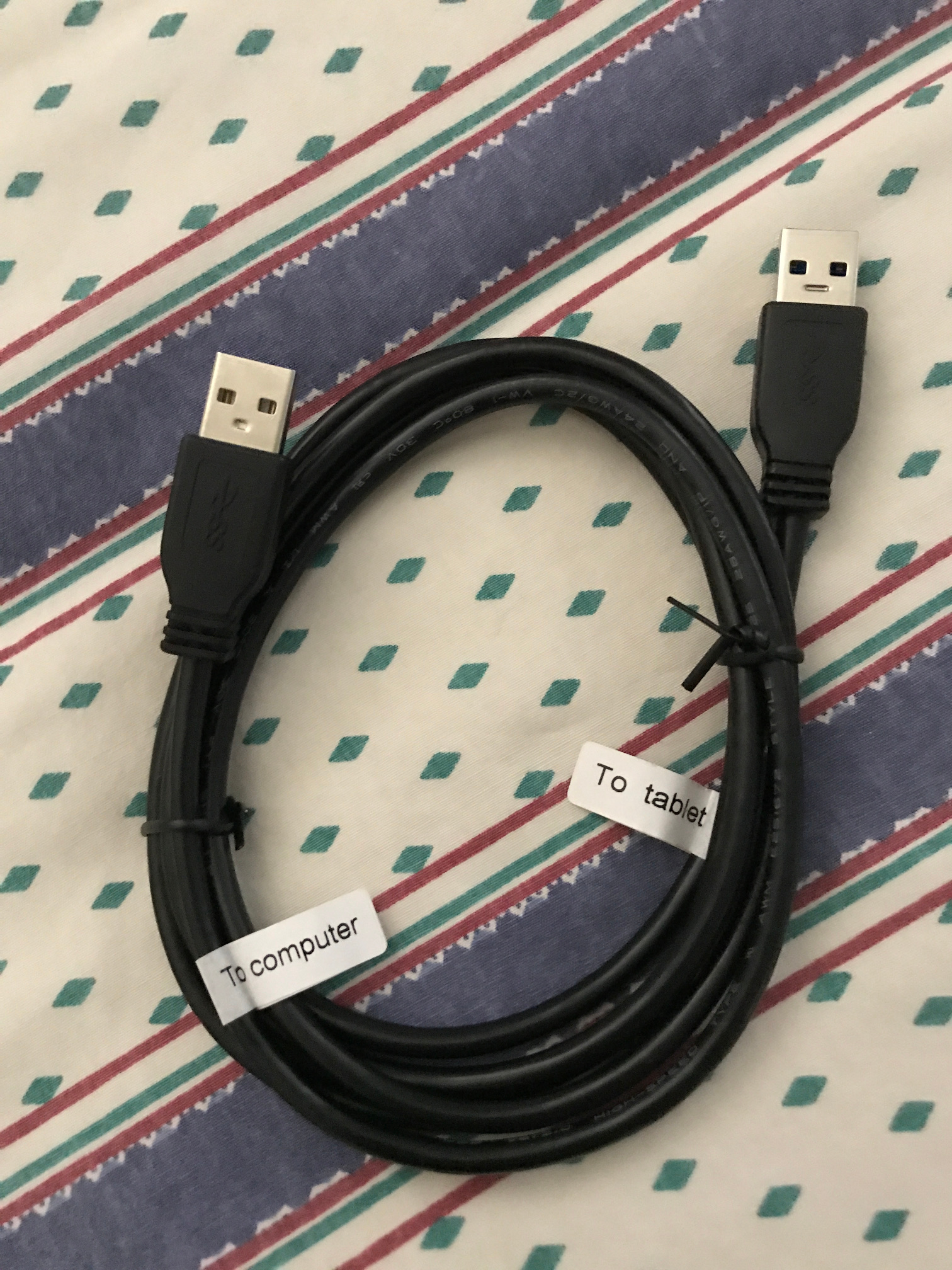
I don’t know if there’s anything special about the cable over other A-to-A cables. The blue end that goes to the tablet appears to be a USB 3.0 connector, which makes sense because USB 3.0 cables are typically blue. So there are extra pins for USB 3.0–but the tablet itself doesn’t actually have connections for any of those pins. I dunno. It’s a mystery. I think they just used a 3.0 connector so they could get one that is colored blue. I think there must be something special about the cable other than just being an A-to-A cable; why else would they mark which end is which? I don’t have an easy way to do any further tests on the cable to try to figure out which pins are connected to which pins.
I guess you could say I made out like a bandit, because the special cable would cost $15 according to the label on the package. The label indicates the product is a “special cable” and it’s for the RCT6513W87, so I assume that tablet has the same problem. For reference for readers, here are the instructions RCA provided me for using the cable:
- Tablet has to be completely off
- Connect the special cable from tablet to computer, please note that the blue end goes to the tablet
- Plug the AC adapter into the tablet
- Turn on the tablet
- Open My Computer to see if PC will recognize the device, if not, please proceed to the next step
- Open Device Manager on your PC
- Choose Portable Devices and select Upgrade Driver Software
- Click on browse my computer for driver software
- Select “Let me pick from a list of a device drivers on my computer”
- Go to Portable Device and choose MTP USB Device
As soon as you do this, your PC should recognize the tablet. [In] some instances, if [your] PC will not recognize the device again, you may have to through the instruction[s] above.
I can confirm that if you start with the tablet turned off and then plug in the cable, it does seem to work properly and enumerate as a USB device on the computer as soon as you turn the tablet on. It worked out of the box with Android SDK on Linux. If you unplug the USB cable, you do end up having to power the tablet off in order to reconnect the USB, so if you do Android debugging, it would be smart to set up Wi-Fi debugging using the steps on this StackOverflow answer.
Hope this helps someone out there!


