I like my EarPods. Yeah, not the new fancy wireless ones. Just the standard wired earbuds that have come with iPhones for a long time. At one point I realized I prefer to use my EarPods during meetings. I was actually using my iPad instead of my computer to join meetings simply because I could use the EarPods.

Read the rest of this entry

Hi again everybody! I’ve decided to combine two blog posts into one: a product review and a new article in my microcontroller programming series. It’s a new concept that I’d like to explore for some of my microcontroller programming articles–concrete examples using actual products. Let me know if you’d like to continue to see posts like this in the future!

Introduction

Thanks to Newark/Farnell, I’ve had the opportunity to review several microcontroller development boards over the past year — see the product reviews category on my blog for more of these. Today, I will be reviewing the LPCXpresso OM11049 board. It’s a very simple development board with a built-in USB programming interface. You can plug it into your computer and use Code Red’s free LPCxpresso IDE to write code, compile it, and flash the resulting binary to the microcontroller. The microcontroller portion of the board is bare–it has nothing connected to the pins other than an LED connected to a single GPIO pin. The rest of the pins are brought out to headers. The idea is that you can create whatever circuit you’d like to use on a breadboard, plug the OM11049 board into your breadboard, and go from there. You can also buy a pre-made baseboard with peripherals already attached (1, 2, 3). For the purposes of this review/microcontroller series post, I’m going to stick with only using the OM11049 board by itself, though.

It comes in a plain-Jane envelope (forgive me, Grandma, for that terrible and inaccurate choice of cliché):

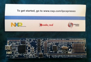
Here’s the board! It’s really long, and there’s a good reason for that. I’ll explain why in just a minute…
For those of you following the microcontroller series, you may be wondering where I’m going with this — it seems like a product review so far. What I’m going to do in the process of reviewing this board is walk through setting up a timer and GPIO as a real-world concrete example with code you can try out for yourself. In addition, I’m going to do it with interrupts, so we can see how to use a timer interrupt to keep track of time. This should apply knowledge you have picked up from my GPIO, timer, and interrupt articles. Ready? Let’s go!

The reason the OM11049 board is so long is because it’s actually two boards in one. The first half (on the left in the picture) is an LPC-LINK debugger, which appears to be implemented on an NXP LPC3154 chip. This half of the board is extremely useful because it allows us to program the contents of the microcontroller on the second half of the board without owning an expensive debugger board.

The other, more interesting half of the board is the target side of the board. This half of the board contains the microcontroller we will be programming. It has an NXP LPC1114/302 ARM Cortex-M0 microcontroller. According to the microcontroller’s datasheet, it can run at up to 50 MHz and it has 32 KB of flash memory, 8 KB of SRAM, one UART, one I2C peripheral, one SPI peripheral, 8 ADC channels, and 28 GPIO pins. For those of you who have been following my microcontroller series, you may recognize SPI and GPIO. For now, you can ignore the UART, I2C, and ADC capabilities — I will talk about them in future articles. Anyway, as I just said, this is a Cortex-M0. It’s very similar to the Cortex-M3 that I have mentioned in previous posts. I really like these types of microcontrollers because they’re 32-bit, easy to use, and common enough to find forum postings by plenty of other people using them when you need help.

In the schematic (see page 34) for the OM11049 board, we can see that there is a red LED connected to pin 23 (PIO0_7/CTS) of the microcontroller. We will need to remember this when we start writing some code.

Just a quick sidenote: you may notice that the LED is not the only thing connected to the pin–there is also a 2K resistor in series with the LED. The reason the resistor is there is because LEDs are only designed to have a certain amount of current running through them. If you allow too much current to flow through, you will blow the LED. The purpose of the resistor is to limit the current that can flow through the LED. (For those of you who took the electricity portion of a physics class, you may remember that V=IR, or rearranged, I=V/R. The higher the resistance [R], the lower the current [I].)

So let’s get started and set up the programming environment! By the way, if you don’t have a USB A-to-mini-B cable, you will need one in order to use the board — it does not come with one. However, pretty much everyone has such a cable these days, so I can’t really fault the makers of this board too much for not including one.

Setting up the programming environment

Install the LPCxpresso IDE, open it up, and follow the supplied directions to register it. Got that done? Good! Now let’s move on.

First of all, we need to import the CMSIS library for the LPC1114. In the LPCexpresso window in the bottom left, there should be a section called Start here with choices such as New project and Import project(s). Click Import project(s). Under Project archive (zip) click Browse. I’m not sure exactly where it will default to, but you want to go into the “lpcxpresso/Examples/NXP/LPC1000/LPC11xx” directory and choose “CMSISv2p00_LPC11xx.zip”. This will install the CMSIS libraries version 2.0. Click Next, make sure CMSISv2p00_LPC1xx is checked, and click Finish.

What is CMSIS?

CMSIS stands for “Cortex Microcontroller Software Interface Standard”.  It basically provides a set of functions and macros that are common between microcontrollers. Imagine you originally use a Cortex-M0 microcontroller from manufacturer #1, and then you decide to change to a Cortex-M0 made by manufacturer #2. A lot of the features between the two processors will be the same because they share the same microcontroller core. You shouldn’t have to rewrite a bunch of your code that works with the microcontroller core just because the two manufacturers organized their libraries differently. The idea behind CMSIS is to avoid the situation I just described by standardizing on the common functionality so it isn’t implemented differently in the libraries supplied by two different manufacturers. If you use a common peripheral like the SysTick timer (which we will do in this article–more on this later), you can expect it to work exactly the same between all Cortex-M0 processors.

It’s more than just that, though. The CMSIS libraries also include startup code that sets up the processor’s clock rate correctly and other similar things like that. They also tend to standardize how peripherals are accessed–the libraries tend to define a struct (e.g. struct LPC_TIMER) that contains all of the register definitions belonging to a peripheral. It further modularizes each peripheral and makes code easier to read. The bottom line is that CMSIS is a very good idea.

It’s not completely perfect, though. If you do SPI (for example) on a chip by manufacturer #1, chances are the SPI peripheral on the chip by manufacturer #2 has a completely different register layout. There’s nothing you can do about this — the peripherals are just plain different and CMSIS does not do any abstraction at this level. So you still end up having to write different code for that kind of stuff. Anyway, that’s enough about CMSIS. Back to the point of this article.

Continuing on…

Now, you’re ready to create a project for the LPC1114. Click on New project in the same bottom-left pane we used earlier. Click the arrow next to NXP LPC1100 projects and choose C Project. Click Next and give your project a name–I chose LPCXpressoTest. Click Next and choose LPC1114/302 as your target. Click Next once again. In the screen that comes up next, you should notice that the CMSIS project we imported earlier is chosen as the CMSIS library to link against. You’re done–click Finish to create the project.

At this point, you have a simple test project all ready to go. In the Project Explorer on the left, find LPCXpressoTest, and expand it by clicking the arrow next to it. Click the arrow next to the src folder that appears, and you should see cr_startup_lpc11.c and main.c.

cr_startup_lpc11.c is a default provided file that handles all of the startup process. It will load any necessary data from flash into RAM when the microcontroller first starts up, and it also provides default interrupt handlers for all interrupts.

We’re not really interested in this file, though — it’s pretty good without any modifications. The really important file is main.c. This is where we can put our own code. It contains the entry point where code will first start running. We’ll also create extra source files that implement smaller (possibly reusable) pieces of the program, so we don’t end up with a single huge file. But before we start coding…

What is this program going to do?

It’s awfully easy to just sit down and start coding (and I’ve done it many times when getting a new microcontroller board), but since I’m writing a tutorial, I suppose I should have some kind of a goal in mind so you know where we’re going. Here’s what this program will do:

  • I want to implement a timer system. Anything can register with the timer and ask to be notified after a specified number of milliseconds have elapsed. Multiple items can be registered at the same time, although we won’t do that in this program.
  • Using this timer system, I want the LED on the LPCXpresso board to blink slowly. As the program goes on, the blink rate will increase until it’s extremely fast, and then go slower and slower until it’s back at the original slow blink rate, and repeat the cycle.

Let’s start coding!

Let’s start by thinking about how to split this program up. The timer is its own complete system, so it should probably be completely separated from the rest of the program. That way, I can reuse it in future coding projects. I’m not going to bother creating a separate module for the LED because it’s so simple, although it would honestly be a good idea in a real program to split it up into its own simple module (even if it’s just a header file with some macros). The idea here is to eliminate creating a single huge file that implements everything. It helps separate responsibilities of the program and increase reusability.

timer.h

Let’s start with the timer. We’ll start with the header file. Right-click on the src directory and choose New->Header File. Name it timer.h and click Done. Easy, right? With timer.h open, we’ll now think about what this system of the code needs to do. First of all, it will need an initialization function. It’ll also need a way for other parts of the program to register with the timer system. In order to keep track of everything registered with the timer, we’ll need to define a struct that contains all necessary info to keep track of registrations.

We’re going to store the timer registrations as a linked list. Something registering with the timer will provide a callback function that will be called when the timer is ready. We’ll also allow a caller to provide a pointer to something that will be passed to the callback. This could end up being useful for future applications, but we won’t use it in this program.

Finally, although the timer itself is interrupt-driven, we will want to use the main loop to manipulate the timer list, so a periodic task will need to check with the timer list to find any timers that have expired and execute their callbacks. Otherwise, we would have to cross the boundary between interrupts and the main loop. For example, when a timer interrupt occurs, we have two choices. If a timer is ready to fire, we could immediately fire its callback from the interrupt handler, or we could signal the main loop which would then handle it the next time it checked all the timers. In most cases, the second option is probably the better option. Otherwise, you would have to make sure all of your callbacks were safe to call from interrupts, and you’d probably also have to worry about modifying the linked list of timers from the interrupt (this tends to overly complicate the functions that add to and remove from the linked list). Plus, the interrupt handler would run for a long time, and shorter interrupt handlers are usually better.

My point is that we will need a function that will periodically be called by the main loop to check if any timers have expired and dispatch their callbacks.

With that in mind, here’s timer.h:

#include <stdint.h>

struct timer {
    volatile uint32_t ticks_remaining;
    void (*callback)(struct timer *, void *);
    void *callback_data;
    struct timer *next;
};

void timers_init(void);
void timers_check(void);
void timer_add(struct timer *t);

(Stick that code inside of the #ifdef and #endif that are automatically generated by LPCXpresso.)

The timer struct will be a struct that anybody registering with the timer will create. The calling code will fill the struct’s callback, callback_data, and ticks_remaining members, and pass the struct to timer_add(). The next member of the struct is used to keep a linked list. The main loop of the program will call timers_check() periodically to find out if any timers have expired. The callback member might look funny if you’re not familiar with function pointers. Basically, it just lets you give the address of a function to the timer system. The function will have the prototype “void blah(struct timer *t, void *data)” This is a commonly-used pattern for implementing callbacks. You tell the timer module what function to call. When the timer is ready, it will call the function for you. We’ll implement that code below so you can see it with your own eyes.

Notice that we made the ticks_remaining member volatile. This is because ticks_remaining will be updated by both the interrupt handler and the main loop, so it’s best to make it volatile to ensure all accesses to it always grab the latest contents from RAM. In this particular case, I don’t think that making it volatile will actually change the generated machine code at all, but it’s a good practice to get in the habit of doing, so we should make it volatile anyway.

Now, let’s implement the actual code that the timer uses. I’ll try to explain how this code works (it helps if you’re familiar with linked lists). Do the same type of thing you did to create the header file, but this time choose New->Source File.

timer.c

#include "timer.h"
#include <stdlib.h>
#include "LPC11xx.h"

static struct timer *active_timers_head = NULL;
static struct timer *active_timers_tail = NULL;

void timers_init(void)
{
    // Turn on the system tick timer with an interval of once per millisecond.
    SysTick_Config(SystemCoreClock / 1000);
}

// Call this function periodically from the main loop.
void timers_check(void)
{
    struct timer *prev_t = NULL;
    struct timer *t = active_timers_head;
    while (t)
    {
        // Has this timer expired?
        if (t->ticks_remaining == 0)
        {
            // Grab a pointer to the next item in the list.
            struct timer *next_t = t->next;

            // Remove t from the list.

            // Two cases:
            // 1) t is the first item in the list.
            // 2) t is not the first item in the list.

            if (t == active_timers_head)
            {
                // t is the first item in the list. Set the head
                // of the timers list to SKIP t. As long as we do
                // this operation first, we won't mess up the
                // interrupt handler.
                active_timers_head = next_t;
            }
            else
            {
                // t is NOT the first item in the list. Set the
                // previous item in the list's "next" pointer to
                // skip t, effectively removing it from the list.
                // As long as we do this operation first, we won't
                // mess up the interrupt handler.
                prev_t->next = next_t;
            }

            // Update the tail pointer if the last item in the list
            // was removed.
            if (t == active_timers_tail)
            {
                active_timers_tail = prev_t;
            }

            // Do the callback for it now that it has been removed
            // and the list is in a consistent state.
            t->callback(t, t->callback_data);

            // No need to update "prev_t" -- it hasn't changed.
            // Move on to the next item in the list, using the saved
            // value of "next" from earlier.
            t = next_t;
        }
        else
        {
            // This timer hasn't expired yet, so just move on to
            // the next item in the list.
            prev_t = t;
            t = t->next;
        }
    }
}

void timer_add(struct timer *t)
{
    // Append the item to the end of the list, so its "next" is NULL.
    t->next = NULL;

    if (!active_timers_tail)
    {
        // First item being added to an empty list
        active_timers_tail = t;
        active_timers_head = t;
    }
    else
    {
        // Item is being appended to the end of a nonempty list.
        active_timers_tail->next = t;
        active_timers_tail = t;
    }
}

void SysTick_Handler(void)
{
    // Here is the interrupt handler that counts ticks.
    struct timer *t = active_timers_head;
    while (t)
    {
        // If we can, decrement the number of ticks remaining.
        if (t->ticks_remaining > 0)
        {
            t->ticks_remaining--;
        }
        t = t->next;
    }
}

Okay. Before you panic, that was a LOT of code. But don’t sweat it. I’m going to go into detail about each function now. First, let’s look at the static variables at the top of the file. We defined head and tail variables to keep track of a linked list of timers. Head will be the first timer, tail will be the last timer. They will be NULL when the list is empty. As far as I can tell, they do not need to be volatile because the interrupt handler doesn’t ever modify them.

 SysTick_Handler

As for the functions, I’m going to start in reverse. Let’s look at the SysTick handler first so we can keep it in mind in the background as we look at the other functions. The SysTick handler will fire once every millisecond. If you’re familiar with linked lists, you will realize this is just a simple implementation of stepping through all items in a linked list. Each item’s “next” pointer points to the next item in the list, until the last item’s “next” pointer is NULL. It decrements the tick counter for each item in the list (but doesn’t decrement it if it’s already at 0–that would cause it to wrap around back to 0xFFFFFFFF, which would be very bad!). Pretty simple, right? Now keep in mind that at ANY point in the main loop of the program when interrupts are enabled, this function could fire. So we need to be careful about how we do things to make sure that the linked list is always in a consistent state while interrupts are enabled — otherwise the interrupt handler could step off the end of an inconsistent list and all kinds of weird behavior would happen. I’ve seen it firsthand in past projects when I made a mistake! I’ll explain what I mean when we look at the timer_add() function below.

Note that this function must be called exactly by the name “SysTick_Handler”. The linker knows that a function with that exact name is an interrupt handler for the SysTick interrupt. Also, as you may recall from my interrupt handlers article, the Cortex M-series are really cool in how they handle interrupts, so your interrupt handler only has to be a standard C function.

timer_add

Now, let’s talk about timer_add(). It’s a really simple function that adds a timer to the end of the linked list of timers. If you don’t follow the logic of what I’m doing in the function, read up on linked lists (in particular, this is a singly-linked list). There are two possibilities when the function is called — either the list is empty, or it’s not. If it’s empty, both the head and tail pointers will be NULL, so we need to set those variables to both point to the item we will add. If it’s nonempty, we just need to set the old tail’s “next” pointer to point to the newly-added item and then update the list’s tail pointer to point to the new end of the list.

Let’s think about this function from the perspective of interrupt safety. We know that at any moment, an interrupt might fire that would step through the complete linked list. In order to keep the list consistent, we must set the new item’s “next” pointer to NULL before adding it to the list. Otherwise, an interrupt could fire after adding it to the list, but before changing its “next” pointer to NULL. If the “next” pointer happened to be some random uninitialized value, the interrupt handler would treat it as a pointer to the next item in the list and continue stepping past the end of the list, eventually probably causing the program to crash when it tried to access an invalid address, or it might end up in an infinite loop if it never happened to access a bad address. Either way, the behavior would be bad news. There would only be a small window of opportunity for a problem to occur (the interrupt would have to fire at JUST the right moment), but when you’re writing interrupt-safe code, Murphy’s Law always applies. Expect the unexpected!

Because the interrupt doesn’t ever access the “tail” pointer, we don’t have to worry about the order in which the tail is modified. But as I explained above, we definitely have to ensure that the new item’s “next” pointer is NULL before putting it into the list. The alternative to careful ordering of operations would be to disable interrupts while modifying the list–but if we can get away with not having to disable interrupts (which we can in this case), that’s the better way to go from the perspective of lessening your program’s interrupt latency.

timers_check

Okay, this is the big function. You might want to open up another window next to this window so you can follow the code as I talk about it. I can’t really think of a great way to put the function inline with this text, so that might be the best plan of attack.

The basic idea of the function is simple, and it’s not too different from the interrupt handler. Loop through every item in the list, and find any timers that have a tick counter of 0 (meaning the timer has expired and it’s ready to fire). The trickiness comes from the fact that this function also removes such timers after calling their callback function.

Not only do we keep track of the current list item we’re at in the loop, but we also keep track of the previous list item. The reason we do this is to make deletions from the linked list easy. When you remove from a singly-linked list, you have to know what item was before the item you’re removing in the list. If we didn’t keep track of the previous item, we would have to write code to step all the way through the list again just to determine which item was before the item we’re removing. That would be a huge waste of processor time, so keeping an extra “previous” variable is a good way to fix that issue. For you CS algorithm geeks who like big O notation: normally, removing an arbitrary item from a singly-linked list is an O(N) operation. Because we’re already stepping through the list anyway to check all of the items, we’ve effectively turned the remove operation into an O(1) operation with the caveat that it’s performed inside a different O(N) operation.

This could also be fixed by making the list into a doubly-linked list where each item has both a “next” and a “previous” pointer (and thus a remove operation is always O(1)), but we didn’t really need that functionality in this program.

Anyway, if an item has expired, it is removed from the list by setting the previous item’s “next” pointer to point to the item after the item being removed from the list. Then, there’s special bookkeeping in case the head or tail pointer has to be updated.

The interrupt safety concern in this function is that the previous item’s “next” pointer (or the head pointer, if we’re removing the first item) has to be updated before ANYTHING else is done to the item being removed. That way, the list will be in a consistent state before and after that line of code. Before updating the previous item’s “next” pointer, the interrupt will step through the entire linked list and skip the expired item because it already has a tick count of 0. After updating the previous item’s “next” pointer to skip the item being removed (which is an atomic operation, so it’s safe to do with interrupts enabled), the interrupt will step through the entire linked list, but it’ll skip the expired item for a different reason: nothing has a “next” pointer that points to it anymore. Once nothing points to it, it’s definitely safe to fiddle with it as much as we want — there’s no way the interrupt will touch it. I hope those last couple of sentences weren’t too confusing — let them sink in until you follow completely, because it’s important.

Back to the rest of the function. Once an item has been removed from the list, we call the callback function on it, and then move on to the next item in the list, repeating the loop until we’ve looked at every item. The callback function might re-add the item to the list (mine does, as you’ll see later). Note: there are certain operations a callback handler could do to the linked list (mainly, removing other items from the list) that could cause problems because the loop’s pointer variables might end up pointing to an item that is no longer in the list. So in this implementation, please don’t remove items from the list inside a callback. A better solution might be to create a linked list of expired timers in the loop, and then go through another loop after the first one, calling each expired timer’s callback. I’m rambling now, but I just wanted to explain that this implementation is not 100% perfect, but it could be fixed. I didn’t want to over-complicate the sample code, but it wouldn’t be right to hold that bit of information back from you, so there you have it.

timers_init

If you’ve made it this far, congratulations. You understand the most difficult part of this whole article. This is the last function belonging to the timer module, and it’s really easy to follow. All it does is enable the SysTick timer and its interrupt.

The SysTick_Config() function is provided by CMSIS, so you can call it on any processor that works with CMSIS. You can also see its source code (it’s in core_cm0.h in the CMSIS project). You provide it with the number of ticks of the SysTick timer that should happen between its firings. In this case, I called it with the parameter “SystemCoreClock / 1000”. SystemCoreClock is a variable provided by CMSIS that tells you the current clock rate of the processor in Hz (in our case, it will be 48,000,000, meaning 48 MHz — this is the default that the NXP-provided CMSIS libraries configure it for, although you can change it). It turns out that the SysTick timer also operates at the same clock rate (well, it can be configured for that clock rate, and that’s how the CMSIS library configures it).

By passing the value 48,000,000 / 1000 = 48,000 to SysTick_Config(), we are telling the timer to fire every 48,000 ticks of the SysTick timer. Since there are 48,000,000 ticks per second, 48,000 ticks comes out to 1/1000th of a second, or a millisecond. That’s how I figured out the value to pass to it.

If you’re in LPCXpresso and you hold down the control key, the SysTick_Config() function should turn into a link as you hover over it. Click with the control-key still held down and it should jump to the source code of SysTick_Config() in core_cm0.h — a nice little trick that I use all the time. You can see that the function sets the LOAD register of the SysTick peripheral, which configures how often the counter will reset. This is exactly the same feature I described in my article about timers when I said that some timers support the ability to reset their counters back to zero after a match. We end up with a repeating interrupt without having to do any cleanup work each time the interrupt fires. (To be exact, I believe the SysTick counter actually starts at the LOAD value and counts down to 0, rather than counting up to LOAD, but the idea is exactly the same–just in reverse.) Other than that, the rest of the function enables the timer and its interrupt. That’s really all there is to it.

main.c

I mentioned main.c earlier, but we didn’t put any code into it. Now, it’s time to get that done. Open up main.c. You should see some auto-generated CRP stuff at the top of the file (that’s for code read protection; leave it in place as is) and a pretty barebones main() function that has nothing but a loop. Here’s our new main.c after adding a timer callback function and modifying main():

#include "timer.h"
#include "LPC11xx.h"

#define LED_PORT LPC_GPIO0
#define LED_PIN  7

static uint32_t cur_delay = 1000;
static uint32_t direction = 0;

void timer_expired(struct timer *t, void *data)
{
    (void)data; // eliminates an unused variable compiler warning

    // Figure out the new blink delay
    if (direction == 0)
    {
        if (cur_delay > 50) cur_delay -= 25;
        else direction = 1;
    }
    else
    {
        if (cur_delay < 1000) cur_delay += 25;
        else direction = 0;
    }

    // Reschedule the timer
    t->ticks_remaining = cur_delay;
    timer_add(t);

    // Toggle the LED
    LED_PORT->DATA ^= (1 << LED_PIN);
}

int main(void)
{
    // No interrupts while we're initializing
    __disable_irq();

    // Set LED as output
    LED_PORT->DIR |= (1 << LED_PIN);
    LED_PORT->DATA |= (1 << LED_PIN);

    // Set up the timer system and add our timer to it
    static struct timer t;
    t.callback = timer_expired;
    t.callback_data = 0; // unused
    t.ticks_remaining = cur_delay;

    timers_init();
    timer_add(&t);
    __enable_irq();

    while (1)
    {
        // Simple main loop. Just check for any timers that have expired...
        timers_check();
        // And wait for the next interrupt to save power.
        __WFI();
    }
}

The first function, timer_expired, is our timer callback function. It changes the delay until the next time it’s called, and reschedules itself. Then, it toggles the LED. This will have the effect of making the LED blink faster and faster, and then when the delay finally reaches 50 milliseconds, it’ll start blinking slower and slower until the delay gets back up to 1000 milliseconds, and then the cycle repeats. Recall that XORing a bit will toggle it. Also, remember when we said the LED was connected to GPIO port 0, pin 7? That’s why we’re referencing LPC_GPIO0, and that’s why LED_PIN is defined as 7.

main() is really simple. __disable_irq() and __enable_irq() are macros (well, actually, static inline functions that end up essentially being macros) that resolve to assembly instructions for disabling and enabling all interrupts. The reason we disable interrupts is to ensure we can initialize everything safely before interrupts start bombarding us. The meat of the main() function is simple. Initialize the timers, add our timer to the list (see how we set timer_expired() as the callback?), and then go into an infinite loop calling timers_check(). __WFI() is another static inline function that resolves to an assembly instruction that tells the microcontroller to wait until another interrupt occurs. It’s not essential, but it probably saves some power (and thus, heat).

Compiling and flashing

Congratulations! You’ve made it through the entire program! To compile it, right-click on the project and choose Build Project. Hopefully, you won’t get any errors (the Console and Problems tabs at the bottom of the window are useful for discovering what’s going on). Assuming it compiles correctly, it’s time to try flashing it.

Plug in the LPCXpresso board, and some drivers may install. Click the Debug ‘LPCXpressoTest’ button in the Quickstart tab in the bottom left corner of the LPCXpresso window. You should eventually end up with a screen showing you paused at the beginning of main() and waiting for you to go. At the top right corner of the window, you should see a button with a green arrow. This is your Resume button. Nearby, there are also buttons such as Step Over and Step Into, just like you would normally see with a debugger. Hover over them and read the tooltips to see what they do. Click the Resume button and your program should happily run. You should see the blink rate slowly speeding up until it gets really fast and starts slowing down again.

When you’re done, click the red square (Terminate) button to exit debugging. That’s it!

Future improvements

This program is all right, but I didn’t put as much time into it as I might have liked. Here are some challenges that I thought of in case you’re bored and feel like working on some programming:

  • Keep the timer list ordered by expiration time, so you only have to check the beginning of the list until you’ve found a timer that hasn’t expired yet. This would increase the time it takes to add an item to the timer list — it would no longer be an O(1) operation — but it would decrease the time taken by the periodic “check” function, which is probably a better optimization.
  • Keep a single global “ticks” variable that’s incremented by the timer interrupt handler. When a timer is added to the list, keep track of what the tick value was at that point (in a member of the struct). Then, just check the difference between the current tick value and the start value until enough time has elapsed. All of that calculation can be done in the main loop, so the interrupt handler does nothing except increment the ticks variable. That’s probably a better way to implement this timer system. I made the code a bit more complicated in this tutorial in order to demonstrate how much fun interrupt safety can be. If anyone is interested (and nobody feels like doing it themselves), I can show a concrete example of what I’m talking about. One thing to keep in mind is that the ticks variable will eventually wrap around from 0xFFFFFFFF to 0. If you use subtraction (now_ticks – begin_ticks) to determine the amount of time that has elapsed, the calculation should still come out fine despite the wrapping.
  • Remove all expired timers from the timer list before calling any callbacks, as I described in my rambling about the timers_check() function. If in the future we added a timer_remove() function that allowed a timer to be removed from the list before it expired, and a callback called that function, the check() function could end up out of sync with the list because the “prev_t” or “next_t” variable might no longer be correct. By removing all expired timers and getting out of that loop before calling any callbacks, the callbacks would be free to do whatever they wanted to the active timers list.

Conclusion

For those of you here because of the review, the LPCXpresso OM11049 board is pretty cool. I love the Cortex-M0 microcontroller on it. The really nice thing about this particular board is they don’t hook anything up to any pins (except for the single LED). If you want to design your own complete circuit, you can do it and not have to worry about pins being used by other devices on the board. That’s really flexible if you’re in the mood for wiring something up on a breadboard. If you solder some 0.1″ pitch headers to the board, it should plug directly into a breadboard. If you’re not into soldering, you can still at least play around with the LED or buy one of the baseboards. Seriously though, I’d recommend soldering the headers onto the board if at all possible. I think you could do some really cool stuff on a breadboard with it. You can buy it at Newark or Farnell.

For those of you here because of the microcontroller tutorial, I hope you’ve had fun with this. I wanted to move away from a bunch of theoretical stuff this time and show some actual microcontroller peripherals in action. I realize that the CMSIS code kind of shielded you from the inner workings of the timer, but I’m hoping that looking at the code of SysTick_Config() helped a little bit. If you take anything from this tutorial, I would say the most important part was the interrupt safety examples and my explanations for why I did things in the order I did them to preserve the interrupt safety of the code. If you understand those concepts, you’re well on your way to practicing safe, interrupt-protected embedded coding!

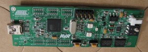
Thanks to the folks at Newark/Farnell, I have been given the opportunity to review another microcontroller development board. This time, it’s the Atmel AT90USBKEY, a cool little USB development board. The AT90USBKEY is powered by the Atmel AT90USB1287 microcontroller. Here are some pictures of the unboxing:

It comes with several cool goodies:

  • The development board itself (which has a USB mini-AB receptacle)
  • A standard USB A-to-mini-B cable that you can use to connect the board to your computer
  • A special USB cable — on one end, it has a USB A receptacle, and on the other end it has a USB mini-A connector
    • I’ve never seen anything like this cable before. The mini-A end of it plugs into the development board, and then you can plug whatever device you want into the “A” receptacle, allowing the board to act as a USB host rather than a device.
  • A 9V battery clip for powering the microcontroller if you’re using it in host mode with the aforementioned cable

Since this board uses some weird (but standard) USB connectors, I’d like to explain them in detail right now before I finish reviewing the product.

USB connectors:

As you probably know, there are normally two major types of USB connectors: A and B. You usually plug a device with a B receptacle into a host with an A receptacle (or a hub with A receptacles). This is why most USB cables you find have an A connector on one side and a B connector on the other side. An A-to-A cable doesn’t make much sense (although I have seen them!), and neither does a B-to-B cable.

You also commonly see devices that have smaller USB receptacles, such as digital cameras and microcontroller development boards. They tend to use mini-B or micro-B receptacles. Because of this, another type of cable is very common: A-to-mini-B and A-to-micro-B. I have tons of these types of cables laying around.

One type of connector you don’t see very often is mini-A or micro-A. They do exist, but they aren’t very common because most computers and hubs have full-size A receptacles. There is a major reason you’d find them, though. Read on…

What about a USB port that is supposed to be either a device or a host, depending on what you connect it to? Should it have an A receptacle or a B receptacle? The answer is “neither.” This is why mini-AB and micro-AB receptacles exist, and it’s called USB On-The-Go. They can accept either an A connector or a B connector (of the required size — mini or micro). Depending on what type of cable you plug in, it will decide whether it should act as a host or a device. In practice, I haven’t seen this type of receptacle on consumer devices, but I see it a lot with development toolkits.

This is the type of receptacle that is on the AT90USBKEY. If you use an A-to-mini-B cable to plug it into your computer, it knows it should act as a device and does so. On the other hand, if you use the other supplied cable that is mini-A-to-A, it knows it should act in host mode, it will behave like one. The USB controller will give you, the programmer, the ability to detect whether it’s currently a host or a device. The A receptacle on the other end of the mini-A-to-A cable just makes it convenient to plug in a standard USB device because you don’t find many USB devices that have a mini-A connector.

I honestly can’t think of any reason for why you would need a mini-A or micro-A connector other than for a USB On-The-Go device, at least as of the time of this writing. Anyway, that is my quick introduction to the AT90USBKEY’s USB port. Enough about that — let’s get on with the review!

The review:

AVRs are very interesting microcontrollers for a number of reasons.

  • First of all, they are well-supported in the hobbyist community. The Arduino project is a good example of this. There are plenty of people making cool hobby projects with AVRs (myself included–more on this in a later post!). There is an excellent set of community-supported development tools for the AVR platform — binutils, gcc, avr-libc, and avrdude are a few of the essentials.
  • They are 8-bit microcontrollers (well, except for some of the newer AVRs). In the 32- and 64-bit world of PCs, it can be kind of strange going back to an 8-bit system. Although C compilers will automatically generate 8-bit code that manipulates larger variables (16- and 32-bit integers, for example), you have to be careful about performance and interrupt safety when working with bigger variables.
  • It gets better — not only are these microcontrollers 8-bit, but they are weird because they have different address spaces for RAM and program instructions (stored in flash), as opposed to something like an ARM microcontroller where everything shares different chunks of the same address space. This requires some weird coding if you’re trying to access constant variables stored in the flash memory, and also prevents you from executing instructions stored in RAM. (Side note: This distinction is sometimes called Harvard architecture versus von Neumann architecture, although modern processors seem to use aspects of both architectures in their designs.)
  • They tend to be very straightforward to program. The built-in peripherals are pretty easy to understand in my experience, and the datasheets that explain the peripherals are pretty easy to read. Recall when I covered the AVR’s SPI peripheral in a previous post–not too bad, right?

Like I said earlier, this board uses the AT90USB1287 microcontroller, which is an 8-bit AVR. You may notice the “USB” in the name. The reason for that is that because you can’t just pick any AVR to be a USB device. This is a chip with all of the necessary hardware built-in to be either a USB host or device, so the name lets you know that. More about this chip: it has 128 kilobytes of flash, 8 kilobytes of RAM, 4 kilobytes of EEPROM, and it can run at a maximum of 16 MHz, although this board only has an 8 MHz crystal on it.

When I said it has 128 kilobytes of flash and 4 kilobytes of EEPROM, you may have been wondering what I meant. What’s the difference? In 8-bit AVRs, flash is designed for code storage and must be erased in large chunks. If you want to erase a byte to write a new value in its place in flash, you must erase many of the neighboring bytes as well. For that reason, it’s not ideal for storing individual byte values that you will have to change in your program. On the other hand, EEPROM is meant for storing data and can be erased on a byte-by-byte basis. The idea is to put your code and large constants into flash because they will only change when you change the firmware. You can put program configuration values that must be saved across power cycles into the EEPROM and not worry about erasing other nearby bytes when you change them.

Aside from the microcontroller, the board also has a small joystick, a temperature sensor, two LEDs (which can each be green or red), two buttons (one is for resetting, the other one is a bootloader entry button which can also be used for your own purposes), and two external memory chips. It comes programmed with a demo application that acts as a mouse and USB disk when plugged into your computer. The demos seem to work great. It also comes from the factory with a USB bootloader, so you don’t even need any extra hardware to program it. The bootloader puts the device into a USB DFU (device firmware upgrade) mode if you’re holding down the bootloader button when it powers on. In order to flash your own program to the board through the bootloader, you will need to use a program compatible with the DFU bootloader — Atmel’s FLIP and the dfu-programmer open-source project are two ways to get it done. I’ll write more about them later in this review. If you want to use JTAG to program it instead, a 10-pin JTAG header came soldered on mine too. For that, you would need a JTAG-compatible programmer such as the AVR Dragon or the AVR ONE!.

Just like I said in my last microcontroller development board review, the demo apps are exciting and all, but the real value in these boards comes when you write your own programs. This can be quite complicated in this case because the most impressive built-in peripheral is the USB controller. USB is a monster of an interface to use for a simple program. Remember when I said earlier that AVRs are straightforward to program? Well, the USB controller is an exception. It’s not Atmel’s fault — it’s just that USB is complicated. Luckily, Dean Camera has come out with a really exciting project called LUFA. It handles talking to the USB controller for you, so all you have to do is work with a higher-level API instead of talking directly with the USB registers in the microcontroller. I’m not going to cover LUFA in this review, but you should definitely check it out.

For the rest of this review, I’m going to walk through getting a development environment set up for programming to this board, and then I will make a simple demo app (although it won’t involve the USB controller — sorry!). We will, however, use the USB capability of the chip to flash your new compiled program using the bootloader. Here goes nothing!

Setting up the development environment:

I really enjoy using Eclipse for my programming, so I’m going to create an Eclipse-based environment. Let’s start out by downloading Eclipse. As of the date of this review, the latest version of Eclipse is Indigo (3.7.1). Download the Eclipse C/C++ environment for your operating system from this page. Extract the contents of the zip archive to a location of your choice. (I’ve found that some versions of Windows don’t like the zip file very well — if you run into any problems, use 7-zip to extract the file instead of the built-in Windows extraction tools).

Open up Eclipse and install the AVR Eclipse plugin using the directions provided on this site. This will make it easy to create cross-compiled AVR projects in Eclipse. (Otherwise, you’d have to mess around with a bunch of C compiler settings to tell Eclipse to use AVR gcc instead of your system’s default gcc)

Now, install the AVR development tools. This will differ based on which operating system you’re using:

If you’re using Windows:

Install the Windows AVR development tools. This will include gcc, binutils, avr-libc, and avrdude. They are packaged together and called WinAVR (note: when accessing this site, I occasionally get redirected to another site because of the webring they are using — if that happens, just click the back button in your browser). Go ahead and download the latest version of WinAVR and install it. Make sure during the installation you check any boxes asking to add WinAVR binaries to your path.

While you’re at it, install Atmel’s FLIP. We will use this to program the new device.

You will probably have to quit and relaunch Eclipse at this point so that it gets the changes that WinAVR made to the system PATH variable. If you don’t relaunch it, it probably won’t be able to find the AVR compiler because it’s still using the old PATH variable.

If you’re using Linux:

Install your distribution’s AVR development tools. In Ubuntu, you can type the command:

sudo apt-get install binutils-avr gcc-avr avr-libc avrdude dfu-programmer

(You don’t really need avrdude right now, but it’s good to have in case you ever start using JTAG or ISP to program AVR devices)

There’s a little more to it, though. Linux can be picky about the permissions of USB devices, so you will probably need to add a udev rule. If you don’t add this udev rule, you will have to run dfu-programmer as root, which is less than ideal. Create the file /etc/udev/rules.d/99-dfu-programmer.rules containing:

SUBSYSTEM=="usb", ACTION=="add", SYSFS{idVendor}=="03eb", SYSFS{idProduct}=="2ffb", MODE="660", GROUP="plugdev", SYMLINK+="at90usb-%k"
BUS=="usb", ACTION=="add", SYSFS{idVendor}=="03eb", SYSFS{idProduct}=="2ffb", MODE="660", GROUP="plugdev"

Once you’ve created the file, type:

sudo udevadm control --reload-rules

The purpose of this last command is to get udev to reread its list of rules. After doing this, the permissions for the USB device should be correct the next time you plug it in. By the way, I got these udev instructions from the AVR Freaks wiki, but their wiki is so slow and messed up right now that I’m not going to bother linking to it.

If you’re using Mac OS X:

Sorry, I’m lazy, but it shouldn’t be too bad. You just need dfu-programmer for OS X and AVR development tools. Looks like this is a good AVR toolkit for OS X. I’m not sure where you can find dfu-programmer, but you could always compile it from source if you want.

Creating the project:

Now, we’re back to a point where it doesn’t matter what OS you’re using. Open up Eclipse. Go to File->New->C Project. A window will pop up. If it’s not already expanded, expand the arrow next to “AVR Cross Target Application” and choose “Empty Project.” The toolchain selected on the right should be “AVR-GCC Toolchain.” Give your project a name and click Next. You’ll notice that Eclipse will create a Debug and Release configuration. You can leave them both on if you want, but I tend to remove the Debug configuration because it breaks some of the optimizations that avr-libc depends on (the delay functions, for instance). Click Next, and then you will be asked to name the microcontroller and clock frequency. The microcontroller is an AT90USB1287. The AT90USBKEY has an 8 MHz crystal and its provided programmed fusebits divide the crystal frequency by 8 to give you a clock rate of 1 MHz by default. However, we’re going to be disabling that prescaler at the start of our code and making it run at the full 8 MHz, so you should type “8000000” into the MCU frequency text box. Finally, click Finish.

If you left the Debug build configuration enabled, make sure that your currently-selected build configuration is the “Release” configuration. Right-click your project in the left column of the Eclipse window and choose Build Configurations->Set Active->Release to select Release. If you don’t do this, the delays won’t work (and you will get build warnings from avr-libc telling you to turn on optimizations or else the delay functions won’t behave as intended).

Now, we’re ready to create a simple project. Let’s blink the LEDs. The code will be very similar to some of my earlier microcontroller programming examples. Before we write the code, let’s do the research and find out what GPIO pins we will need to play with.

According to the AT90USBKEY hardware user guide, the LEDs (D2 and D5) are bi-color LEDs connected to PORTD:

  • D2
    • Red is connected to PORTD, pin 4
    • Green is connected to PORTD, pin 5
  • D5
    • Red is connected to PORTD, pin 7
    • Green is connected to PORTD, pin 6

They behave just like they are separate LEDs. So in effect, you have four LEDs available, although each pair of green and red LEDs overlap with each other and look kind of strange when they are both on at the same time. Anyway, this is all we need to know to get a simple program running. Let’s do it!

Create a new C file by right-clicking on your project in the left column of your Eclipse window and choosing New->Source File. Name your file main.c and leave the template as the “Default C source template.” Type (or copy/paste, if you’re not masochistic) this code into main.c:

#include <avr/io.h>
#include <util/delay.h>
#include <avr/wdt.h>
#include <avr/power.h>

#define LED_PORT                                PORTD
#define LED_PORT_DDR                            DDRD
#define LED_PIN                                 PIND

#define LED1_RED                                (1 << 4)
#define LED1_GREEN                              (1 << 5)

#define LED2_RED                                (1 << 7)
#define LED2_GREEN                              (1 << 6)

int main(void)
{
    // In case the watchdog timer is enabled, disable it.
    wdt_disable();

    // Make sure the clock prescaler is disabled (divide by 1)
    clock_prescale_set(clock_div_1);

    // Set the LEDs as outputs and turn them all off
    LED_PORT_DDR |= LED1_RED | LED1_GREEN | LED2_RED | LED2_GREEN;
    LED_PORT &= ~(LED1_RED | LED1_GREEN | LED2_RED | LED2_GREEN);

    // Turn on LED1's red output and LED2's green output
    LED_PORT |= (LED1_RED | LED2_GREEN);

    while (1)
    {
        // Wait and then toggle all four LEDs
        _delay_ms(1000);
        LED_PIN = LED1_RED | LED1_GREEN | LED2_RED | LED2_GREEN;
    }
}

Now, compile the program by going to Project->Build All. This command actually builds all open projects, but since this is the only project we have open, it will work. You may see some weird errors about DDRD and PORTD being undefined — if so, it’s probably Eclipse whining about it rather than the compiler. Rebuild the index by right-clicking on your project and choosing Index->Rebuild — hopefully those errors will go away. Anyway, you should have a .hex file inside the “Release” folder ready for flashing.

I want to share a quick note about this code before we get to the rest of the flashing. Did you notice that I write to the PIND register to toggle the LEDs inside the while loop? Normally, this register is used for reading the state of port D’s input pins, and you would use PORTD to change the state of the output pins. AVRs have a cool feature — if you write a “1” to a bit in an AVR’s PINx register, it will actually toggle the value of the corresponding bit in the PORT register. Any bits that are 0 are unaffected. It’s just a handy little shortcut that probably doesn’t apply to other microcontrollers, but it does work on several different AVRs that I have used. The code generates results identical to (but is more efficient than):

LED_PORT ^= LED1_RED | LED1_GREEN | LED2_RED | LED2_GREEN;

Enough about that — back to flashing!

Flashing your code to the board:

If all went well, you are ready to test your newly-created firmware project. First of all, let’s get your AT90USBKEY board into its bootloader. Connect the board to your computer. Now, while holding down the HWB button on the board, press the RST button on the board. This forces the AT90USB1287 to boot into its supplied USB DFU bootloader. Alternatively, you could also just hold down the HWB button while plugging the board into your computer.

Now, we need to break off depending on which OS you’re using again:

If you’re using Windows:

Open up Flip (you installed it already, right?). Click the leftmost icon in the toolbar (looks like a DIP chip) and select AT90USB1287 as your target device. Now, click the second icon from the left (looks like a USB cable) and choose USB. A dialog box will come up–click Open. All of the buttons in the Flip window should be enabled now. You’ve made contact with the bootloader! Click the third icon from the right (looks like a book with an arrow pointing down) to load a hex file to download to the device. Navigate to your Eclipse workspace and find the YourProjectName.hex file. It should be in the Release folder inside your project’s folder. This will load the .hex file into Flip’s buffer, but won’t program it yet.

On the left side of the Flip window under Operations Flow, make sure Erase, Program, and Verify are checked. If they are, click Run. If all goes well, the status bar in the bottom of the Flip window should say “Verify PASS.”

If you’re using Linux:

This should be pretty easy, assuming you have already configured dfu-programmer correctly. Type:

dfu-programmer at90usb1287 erase
dfu-programmer at90usb1287 flash /path/to/my/projectfile.hex

(Of course, replacing /path/to/my/projectfile.hex with the path to your hex file.) That’s it!

If you’re using Mac OS X:

Once again, I’m lazy. You should be able to use the same directions as Linux if you can get dfu-programmer up and running.

Running your code:

You have now successfully programmed your firmware onto the board. Press the RST button on your board and watch as your program runs and toggles the LEDs every second. Easy, right? If you want the original firmware that came on the board, you should be able to get that back by flashing one of the provided .a90 files from Atmel’s AVR287 example. To be safe, it might be wise to back up the supplied contents of the mass storage device that the board’s default firmware creates before loading your custom firmware.

Conclusion:

I have now shown you how to get a simple program running on the board. Download LUFA, play around with it, and see what you can create! Atmel also provides some USB libraries, although I haven’t played with them.

As far as this board goes, it’s fantastic. It gives you plenty of fun devices play with. You can learn about GPIO pins with the LEDs (outputs) and the joystick (inputs), you can learn about analog-to-digital converters (ADCs) with the temperature sensor, you can learn about SPI with the two serial flash chips, and you can of course learn about USB.

Pros:

  • It’s really easy to get running without needing any external programmer hardware. It’s basically unbrickable.
  • They provided some handy (exotic?) cables to give you the opportunity to play with the board as either a USB host or device.
  • Atmel made creative use of the USB capability by providing all documentation and software on the device itself as a mass storage device that appears when you plug it in.
  • It has awesome community support because it’s an AVR.

Cons:

  • The DFU flashing software (particularly Flip) is kind of confusing and annoying to use. It’s a lot more convenient to develop with JTAG or ISP because you don’t have to physically mess with the board whenever you want to write a new program to it. It would also be nice to integrate this flashing with Eclipse. I’m sure it’s possible with a custom run configuration and a script.
  • They brought the other port pins out to very tiny headers. It appears that headers would be difficult to solder, and it would be a challenge to find the correct header part for soldering. It would be nice if they used standard 0.1″ pitch headers instead, although that would obviously come at the expense of a larger board size.

You can buy an AT90USBKEY at Newark. Thanks again to Newark/Farnell for the opportunity to review this cool little development kit!

I recently had the opportunity to get a Freescale KwikStik Kinetis K40 Cortex-M4 development board (thanks, Newark/Farnell!). I’ve been using the Cortex-M3, so I had been very excited to test out the Cortex-M4. Plus, I have also been anxious to evaluate Freescale’s ARM offerings, so this was the perfect board for that. Sadly, the Cortex-M4 included in the K40X256VLQ100 chip used on the KwikStik does not have the optional floating-point unit, so I wasn’t able to do any performance tests as far as that is concerned.

Anyway, I thought I’d share my experience with the board, so here goes nothing!

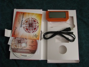
It came packaged in a nifty box that opens up to reveal two sides — one with some documentation and a getting started DVD, the other with the Kinetis in its awesome cover and a USB A-to-micro-B cable:


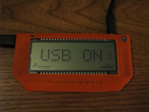
Here is the KwikStik, powered up in all its orange glory:

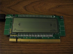
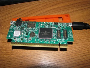
And here it is outside of its case:


The DVD contains various PDF datasheets for the Kinetis microcontrollers, evaluation and code-limited versions of several compilers, and Freescale’s MQX RTOS.

Freescale put a ton of interesting things on the KwikStik to play around with:

  • LCD display
  • 3.5 mm audio output jack
  • Microphone
  • Buzzer
  • Onboard USB J-Link programmer for flashing the chip (and to use the board as a programmer for other boards)
  • USB OTG/host/device port for applications
  • Infrared transmitter/receiver
  • microSD card slot (doesn’t totally work in the revision I received — see below)
  • Six capacitive touch buttons
  • Rechargeable MgLi (manganese lithium) coin cell battery

So without further adieu, let’s get started with the fun stuff!

When you power the board up with the default firmware by plugging into either of the two USB ports, a menu comes up with three options, navigable with the capacitive touch buttons. The options are: sound recorder, remote control, and USB joystick.

The sound recorder will record two seconds of audio with the built-in microphone and play the recorded sound back through the 3.5 mm jack. The remote control feature is meant for controlling a Sony TV, and the USB joystick will let you use some of the capacitive touch buttons as a simple HID joystick on a computer.

Unfortunately, I couldn’t get the HID joystick demo to work — it was recognized on the computer as a gamepad, but the buttons wouldn’t register any presses in the Windows 7 game controller settings dialog. I also couldn’t test the Sony TV controller since I have a Vizio TV. The sound recorder works fine though!

The default firmware doesn’t really matter much, though — the fun part is making your own programs to do stuff! To start out, I downloaded CodeWarrior Development Studio for Microcontrollers (Special Edition with 128K code size limit). I had to download it since it didn’t come on the DVD. Installing it was a bit of a pain because I later found out that putting it in the default C:\Program Files (x86) directory will cause problems later on when trying to update it, so I had to uninstall it and put it in a standard unprotected location where administrator access isn’t needed to modify files. Despite that annoyance, I like it because it’s based on Eclipse and I’m used to Eclipse. I also tried IAR, but I didn’t like the user interface (and couldn’t get it to work with the demo firmware anyway). I also downloaded the Segger J-Link software — Segger’s site seemed to imply that my DVD should have come with it, but I couldn’t find it as an option to install in the Flash interface. Luckily, Segger still lets me download it as long as I agree not to use it with illegal cloned boards. So I got that all ironed out!

Despite not caring too much about the default firmware, the first thing I did was download the factory image off the device, just in case. After installing the Segger software, I used JLink.exe to read the flash contents after using JMem.exe to determine where the flashed image ended (where a bunch of endless 0xFFs began). It turns out the firmware binary is 0xD004 bytes long, so I used these commands in JLink.exe:

h
savebin C:\Path\To\DefaultFirmware.bin, 0x0, 0xD004

The “h” command halts the CPU, and the “savebin” command will save 0xD004 bytes of data starting at address 0 to DefaultFirmware.bin, so I can always restore the board back to the exact way I got it. Yeah, I’m paranoid like that. It’s always the first thing I do when I get a microcontroller evaluation board. The way I see it, I’m going to need to know how to use the flashing/debugging tools anyway, so it’s not a waste of time to do that first!

Next, I decided to try to compile Freescale’s example firmware to see if maybe they had worked out some of the kinks in the HID joystick demo. This required updating CodeWarrior to the latest version and installing the latest version of Freescale’s MQX RTOS, which the demo uses. Finally, after trying to compile the example firmware, I ran into some errors because there were a couple of hardcoded “C:\Program Files” paths which I had to change. After all that mumbo jumbo, I was finally able to compile their example firmware which is available for download on the KwikStik page on their website.

Programming the device from inside CodeWarrior worked fine, and once that was done, I ran the demo — they actually had replaced the HID demo with a USB mouse demo, which does work (it lets me left click and right click). They had also fixed a bug that caused the remote control app’s exit button to not work, and they added a Tetris clone game demo.

OK, so at this point I finally had an environment ready for doing some real development! I didn’t really feel like learning how to use Freescale’s RTOS yet, so I just made a simple bare metal demo app to turn on all the LCD’s segments in succession, then turn them off in succession, endlessly.

CodeWarrior comes with some pretty interesting features — the microcontroller appears as a picture in CodeWarrior, and the picture contains a bunch of blocks for all the peripherals built in, including the CPU itself. You can click on them to set up options (such as clocking for the CPU) and it will generate initialization code for you. It made it pretty easy to make a quick app. I borrowed some of the code from the KwikStik demo application for the LCD to understand the options Freescale used for setting it up, and it pretty much worked right out of the box. It turned out that the LCD was visibly flickering in my app, and it was because I had to change the IRCLK source to be the fast internal reference clock (2 MHz) instead of the default slow internal reference clock (32.768 KHz) — it looks like the SLCD’s initialization was using the IRCLK and the default setting was not fast enough, so I saw flickering. With that out of the way, my program worked like a charm!

After all the initialization is complete, here’s the simple main loop code:

int x;
int y;
volatile int c;

for (;;)
{
    for (x = 1; x < 40; x++)
    {
        for (y = 0; y < 8; y++)
        {
            // Turn on the segments one at a time...
            LCD_WF8B(x) |= (1 << y);

            // Wait a bit?
            c = 0x20000;
            while (c--);
        }
    }

    for (x = 1; x < 40; x++)
    {
        for (y = 0; y < 8; y++)
        {
            // Turn off the segments one at a time...
            LCD_WF8B(x) &= ~(1 << y);

            // Wait a bit?
            c = 0x20000;
            while (c--);
        }
    }
}

I like the SLCD peripheral! It makes it easy to turn segments on or off by changing a single bit, and then you’re done. The SLCD peripheral uses up to 8 pins as backplane pins, and the other 40 pins can be used to control 40 segments per backplane. It is very quickly switching between the eight backplanes and turning the segments on and off as necessary. This all happens so fast that you have no idea that the LCD segments are being turned on and off (well, unless you accidentally set the clock rate too low like I did!). With 8 backplane pins and 40 segment pins, you can control up to 320 LCD segments with this peripheral. It would be a big pain in the rear end to implement the LCD refreshing I just described manually, and the peripheral makes it so easy — just set the bit for the segment you want to turn on, and you’re done!

The next thing I should do is get rid of the ugly busy waiting that I have for delays right now, and switch over to using a timer, which would be pretty easy to do.

So yeah, once you get down to making your own stuff, it’s a cool little board with tons of possibilities for interesting applications!

Now, remember how I said the SD card slot doesn’t totally work? Well, it turns out that in board revisions earlier than revision 5 (I received revision 4), Freescale accidentally connected the SD card socket’s data pins to the wrong pins on the microcontroller! It essentially makes the microSD card slot useless because you can’t use the Kinetis’s built-in SDHC controller peripheral for accessing the SD card. You could bit-bang it yourself, but that will have a (very negative) performance impact. Maybe I can hack the board with some cut traces and wires to connect the SD card socket’s pins to the correct microcontroller pins — who knows? Maybe I’ll do THAT as a fun project soon! If I do, I’ll be sure to post about it here!

So, in conclusion, I’m happy with the board, although it seems like Freescale made a really boneheaded mistake (the SD card wiring problem is inexcusable, especially given that it was still present in revision 4 of the board!). Regardless of that, though, I’d still definitely recommend it as a platform for learning about microcontrollers, simply because of all the awesome stuff it has built-in aside from the microSD slot. And seriously, a 100 MHz processor in a microcontroller? I know the Cortex-M3s were up there in clock speed too, but still–what’s the world coming to? With all of that processing power combined with the wide range of peripherals, it provides plenty of awesome opportunities to learn about microcontroller programming. The included orange protective jacket is a nice touch, too!

You can purchase the Kinetis KwikStik from Newark.

Until next time, see ya later!

I haven’t written about my Mac ROM hacking lately, so this post will double as an update to my ROM hacking endeavors and a review of Seeed Studio‘s awesome Fusion PCB service.

After going through all the hoopla to desolder the DIP chips on my Mac IIci and socket them, I finally got frustrated. The main annoyance is that the DIP ROMs are all the way underneath the hard drive and floppy drive carrier. It was forcing me to basically rip everything out of the IIci in order to access the DIP sockets. I also had been in contact with the folks on the 68k Mac Liberation Army forums, and they had a lot of useful information, including the tidbit that many of the Mac II series machines (and the SE/30) have a SIMM socket that you can put a ROM SIMM into. My IIci also has this socket, and it’s easily accessible without removing anything from the case. So, I decided to make my own! Thanks to a lot of advice from fellow forum members, I was able to lay out a SIMM printed circuit board to have manufactured.

I ran into a problem: the SIMM needs to be about 0.047″ thick in order to physically fit in the socket. Most of the inexpensive circuit board prototyping manufacturers make boards that are 0.063″ thick. Luckily, bigmessowires from the 68k Mac Liberation Forums was able to recommend a PCB manufacturer that could make the boards in the thickness I needed: Seeed Studio Fusion PCB. He had used them in the past with good results, so I went for it.

Seeed Studio has amazing pricing. My board was about 3.85″ by 1.1″. That fits within a 10 cm by 5 cm rectangle. As of this writing, they can manufacture ten 2-layer boards of that size for a total of $24.90 plus shipping. That includes solder mask and silkscreen on both sides. It’s an incredible price! They also offer many thickness options, including 1.2 mm, which works out to 0.047″. I asked for red solder mask instead of the standard green, which added an additional $10 to the price. They have extremely good trace width/spacing requirements: 6 mil (0.006″) trace width and 6 mil spacing. I went ahead and made my minimum trace width and spacing 8 mils, just to be safe.

After you place your order online, you e-mail them a zip file containing the Gerber files for your PCB. If there are any problems, they will let you know — otherwise, you just have to wait for the boards to be manufactured and shipped.

Shipping was only $3.52 for registered air mail to the United States from Hong Kong. They had other options, too, but this was the least expensive one. They take PayPal as a payment option, and I can’t remember the other options they offered. I placed my order on the night of Monday, September 5, they shipped my board on Tuesday, September 13, and the package arrived on Friday, September 23.

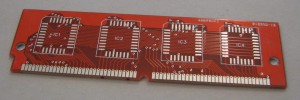
I’m sure you’re wondering: how did the boards turn out? Well, they turned out just fine! As you can see, they were able to manufacture a board with an irregular shape:

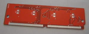
You may see some numbers on the silkscreen. Seeed Studio’s directions tell you to add your order number to the silkscreen somewhere, so I did that on the bottom. They also added a few other numbers onto the top silkscreen. Not a big deal at all, especially for the price!

Electrically, the SIMM tested fine. All the traces were perfect. Seeed Studio will electrically test 5 of your boards for free, and you can pay to have the other 5 tested, too.

Oh, did I mention that they actually sent me 12 boards instead of 10? How cool is that?

I would highly recommend them if you are looking for budget PCB fabrication. They only do 1 or 2 layer boards, so you can’t do anything overly fancy with 4 or more layers, but 2 layers is plenty for all kinds of fun stuff you can make, such as this SIMM.

By the way, my SIMM ended up working perfectly, and it expanded my IIci’s ROM capacity to 2 MB (the original ROM is only 512 KB). I naturally tested the rest of the capacity by filling the remaining 1.5 MB with the Super Mario Bros music and turning it into the longest Mac startup chime ever:

If you’re curious what the assembled board looks like, I show it off briefly in the video.

So anyway, all in all, I had a very positive experience with Seeed Studio’s Fusion PCB service! I was shocked when I saw the pricing, and I am very happy with the boards I got back. Thanks, Seeed Studio!