I can’t remember exactly why, but I recently decided I wanted to play around with Super Nintendo games that support more than two players. I have a Super Nintendo console along with several such games — Super Bomberman, NBA Jam, and Madden 97 come to mind. The most popular adapter designed for this purpose is called the Super Multitap. It plugs into the second controller port on the SNES and provides four controller ports, so you get a total of five ports available for use.
I looked on eBay for Super Multitaps and found plenty for sale, but I decided I wanted to make things more complicated. I stumbled upon a schematic for it, found in the official Super Nintendo developer manual. Google for it if you’re interested — I don’t want to link to it just in case lawyers want to ruin all of the fun. I was intrigued by the simplicity of the circuit. It’s basically 3 chips (a mux and a bunch of tri-state buffers), eight resistors, and the controller connectors. Why buy the ready-made adapter if I could just make my own? In theory, buying the parts would be cheaper than buying a used Multitap on eBay, but in practice, the controller sockets and plugs are hard to find so it’s probably not worth it from a monetary standpoint.
But still, I think it’s worth it for the geek cred! Right?
Well, I decided to do it.
First of all, here’s a video showing it in action with the three games I listed above.
Now I’ll provide all of the details. I started out by reviewing the schematic and figuring out what exactly I needed:
- 74HC4053 triple 2-channel analog mux (it’s an analog mux, but it’s being used as a digital mux, which is perfectly OK to do)
- 74HCT126 quad independent tri-state buffers
- 74HCT241 non-inverting octal tri-state buffers with two output enables
- Eight 10kΩ resistors
- Four SNES controller sockets
- An SNES controller plug
- A 4PDT switch (I omitted this part because it would have been annoying to connect and is only useful for allowing to switch between 2-player and 5-player mode — I don’t care about 2-player mode!)
- An LED and resistor (I omitted these because I don’t care about the LED)
- It’s probably a good idea to add some bypass capacitors for the chips and perhaps some extra capacitance which the circuit recommends for the VCC pins connected to the extra three controllers.
Luckily, all of the parts with the exception of the controller sockets and plugs were available as through-hole parts. I didn’t want to throw together a PCB, so I decided to breadboard it!
Because two of the chips contain tri-state buffers that are spread all throughout the circuit, it’s hard to divide the chips into distinct stages. Thus, the breadboard is a spaghetti nightmare. I had to design it ahead of time on the computer. I’m pretty sure it would have been nearly impossible to do it without a design laid out first. I found a really cool program called Fritzing that can help you lay out a breadboard ahead of time. It can also create schematics and PCBs — cool! It felt very user-friendly compared to other schematic/PCB layout programs I have used in the past.
Here’s my completed breadboard layout (click to view any of these smaller images full size):
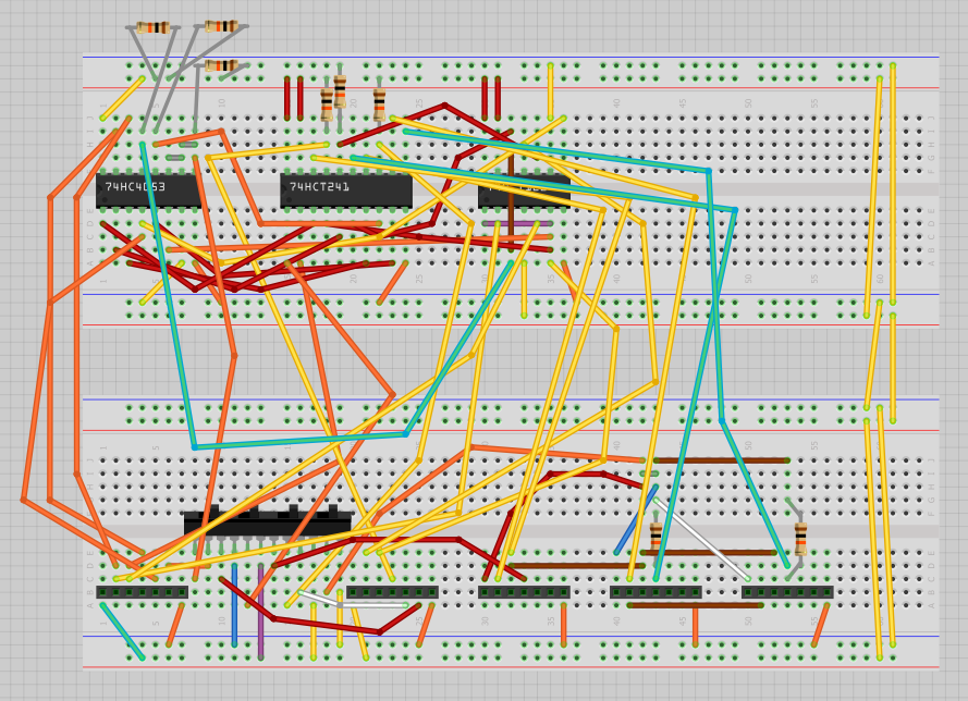
I colored the wires black initially. As I placed each wire, I changed its color to match the actual wire color and moved it to match approximately how it was placed on the actual breadboard. What you see is the final result I was left with inside of Fritzing after I finished placing every wire into the breadboard.
You can see the four switches near the bottom left corner of the picture. They were supposed to represent the 4PDT switch. Instead, I just hooked it up to force the switches into 5 player mode on the actual breadboard. The headers near the bottom are the controller ports. The one on the left is the connector that plugs into the SNES, and the four on the right are the sockets where the SNES controllers plug in.
Here is a download of my Fritzing breadboard file if you want to assemble one of these for yourself. The schematic view and PCB view aren’t finished, but the breadboard view is completely laid out.
Here are some progress shots as I placed the wires and components onto the breadboard:
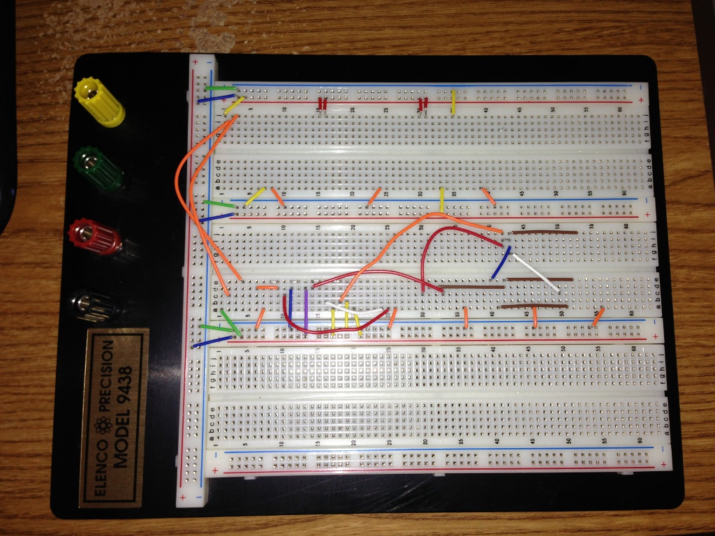
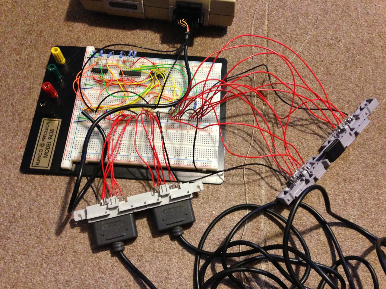
I got as far as the image above, then had to wait until the chips arrived. When the chips arrived, I placed them and continued on with the rest of the wires:
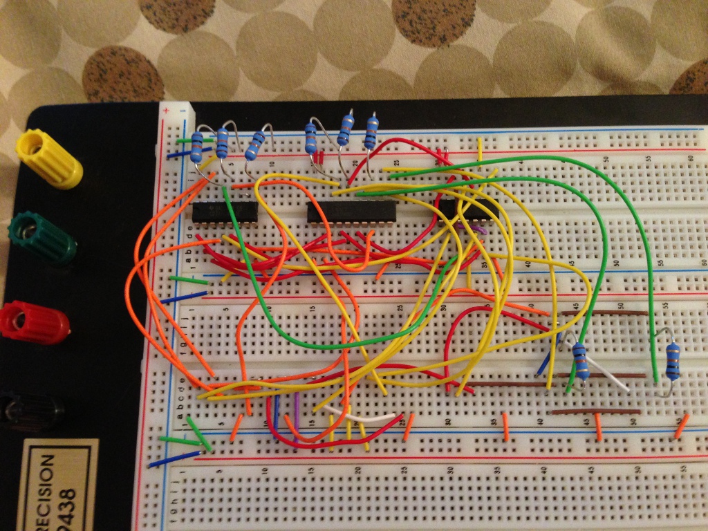
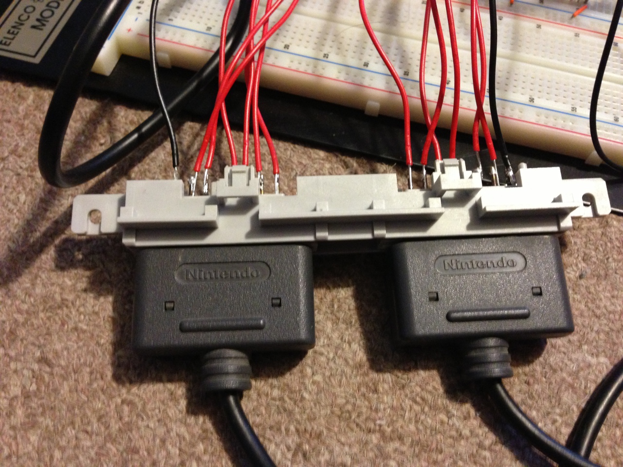
OK. At this point, the multitap schematic was complete. I just had to hook up the SNES controller connectors. For the four sockets, I bought a pair of original SNES front port assemblies on eBay. I desoldered them from their circuit boards (although I probably could have left them attached and it would have worked fine) and soldered wires to them. I connected the other end of each wire to the breadboard. For the connector that hooks up to the SNES, I bought an SNES controller extension cable and cut it up.
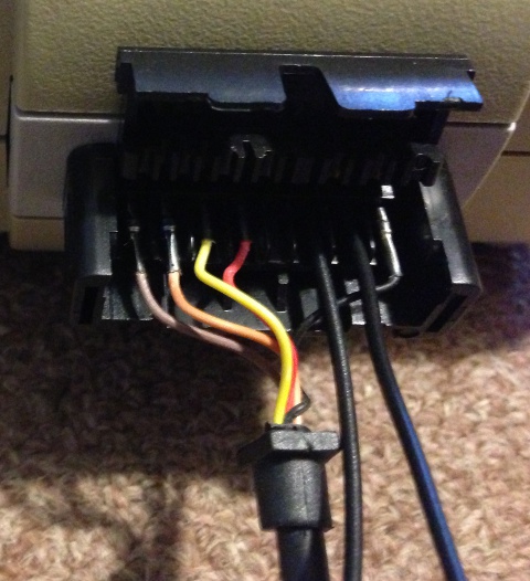
Unfortunately, I ran into a snag with the extension cable. SNES controllers only use five of the seven pins in the controller connector. The other two pins are necessary for the SNES Multitap to function. Data is read serially from each controller on a single pin. On the SNES multitap, a mux is used so you can alternate between different controllers when reading the data from them. Controllers 2 and 3 are connected through the mux to the original data pin, and one of the two extra pins is used as the data pin for controllers 4 and 5 (also through the mux). The other extra pin is used for controlling the mux. So the SNES reads simultaneously from controllers 2 and 4, switches the mux, and then reads simultaneously from controllers 3 and 5. At least that’s what I believe after reading the schematic. Anyway, because actual controllers don’t use those other two pins, extension cables don’t include them. So I had to tear apart the extension cable and add two really ugly wires to make the connection to the other two pins. I have to carefully hold them in as I plug my multitap into the SNES. I think for a prettier solution I will need to buy another extension cable and gut it to steal two more pins. Alternatively I might be able to find two more pins to insert into the connector.
The final setup plugged into my (yellowed) SNES:
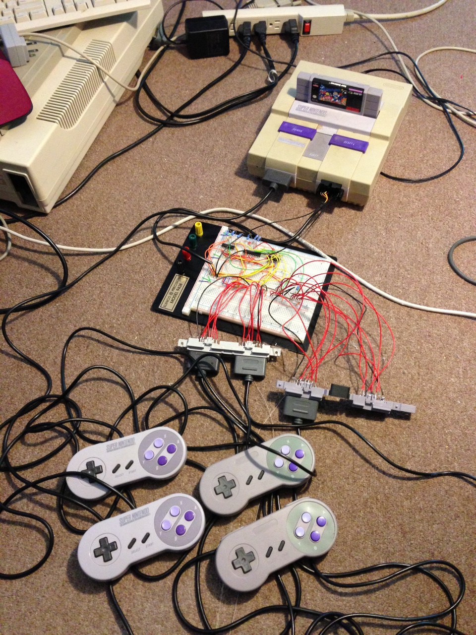
Looks like some Retr0bright might be in my SNES’s future!
I only had two original SNES controllers, so I bought a couple more cheap knockoffs on Amazon. Super Bomberman correctly detects controllers hooked up to the SNES’s port 1 and my breadboard’s controller ports 2 through 4. Success! (It’s not 5-player compatible, so port 5 doesn’t do anything) Gameplay works perfectly with all four controllers.
With my initial test, Super Bomberman worked fine, but Madden 97 and NBA Jam acted like there was no multitap connected — except Madden 97 still allowed navigating the menu with the other controllers! Weird! So the actual multitap data was getting through, but some games were ignoring it. After some research, experimentation, and frustration, I narrowed down the problem to the fact that the multitap wasn’t identifying itself back to the SNES correctly when the OUT0 pin was high. If you read the schematic, when the SNES drives the OUT0 pin high, the multitap circuit should spit a low value back to the SNES on D1. The OUT0 pin being high activates a tristate buffer that hooks D1 to ground. That wasn’t happening. Sure enough, I had miswired one of the breadboard wires. It’s actually wrong in all of my pictures too. Near the top, if you see the yellow wire going into row J, column 37, you might notice column 37 is not attached to anything else. That wire was supposed to go into column 36. It connects the output of the tristate buffer back to D1. With the wire in the wrong place, D1 was floating when the OUT0 pin was high, rather than being driven low by the multitap circuit.
In the process of debugging this issue, I also added some capacitors, which I probably should have done initially. That wasn’t the actual fix though. The incorrect wire was the problem. After fixing the wire, NBA Jam and Madden 97 now work perfectly with all of the controllers too. Woohoo! My guess is that Super Bomberman worked because it still tries to read controller data from a multitap even if the multitap doesn’t identify itself correctly, and same with Madden 97’s menu.
So it works. Would this be a way to save money? It definitely would be, but only if the SNES controller sockets and plugs weren’t so hard to find. The majority of the money spent on this project was for those. In total, I spent about $32 including shipping just for those connectors. Ugh. I probably could have spent less money if I had just bought four extension cables on Amazon, especially considering that the four sockets don’t need the extra two pins in 5-player mode. The actual components I put on the breadboard were dirt cheap. It was less than $5 worth of parts. If the connectors were readily available, this would have been a super deal! Instead, it was just a fun little project.
Another drawback with this route is that it’s really easy to make a mistake when you’re breadboarding things, like what happened to me. Honestly, I’m amazed I only screwed one wire up. Creating a circuit board would have been the smarter way to go, but it was also fun making a huge web of wires. Here are a few more pictures for your viewing pleasure:
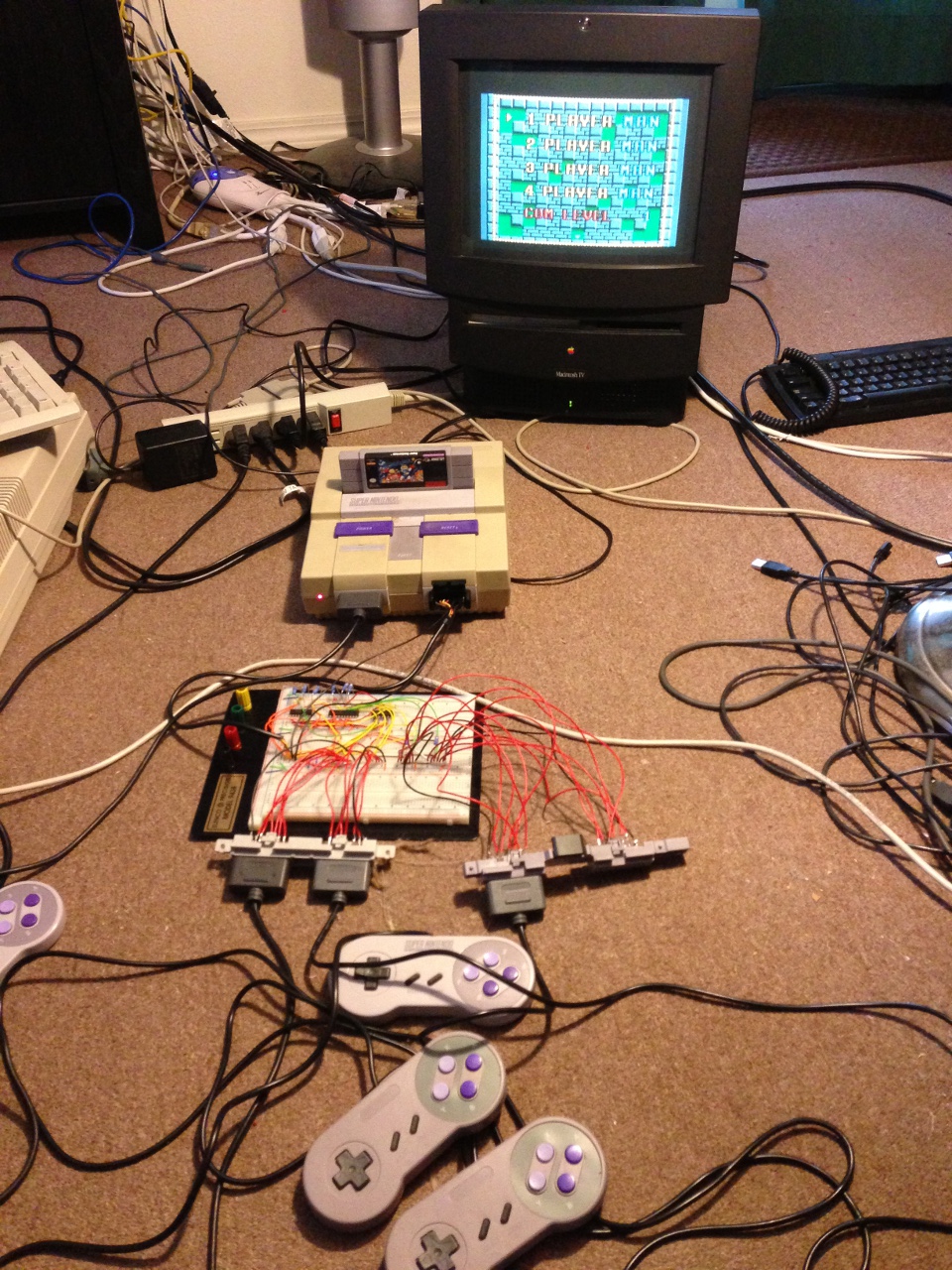
Yes, that’s a Macintosh TV it’s plugged into. If you view the larger version of the image you can see Super Bomberman correctly detecting all four controllers on its screen.
Also, I realized after the fact that I didn’t need to wire up all seven pins on the four controller sockets. Two of them are disconnected on every socket (the same two that are left out of the extension cables). Well, except for the first socket, but only when you’re in 2 player mode. But like I said earlier, I hardwired it for 5 player mode, so I could have skipped those pins on all four sockets. Anyway, I digress.
Am I nuts? You tell me!


Hey this is an awesome project and i cant wait to get it started. I have one question though. With the switches , is it one switch that controls the others or is it four separate switches? Looking at images of old mulitaps has only one switch. So im just wondering if there are inertial switches that all run to the one switch. I hope that makes scene.
Hey Jeremy,
There is one switch, but in circuit it acts like it is four switches that are simultaneously being flipped. It’s called a 4PDT switch (4 pole, double throw). So you flip a single switch and internally it acts like four completely isolated switches have all been flipped at the same time.
Hey! I’ve decided to pick up where you left off on this. I’m wondering if you had an updated Fritzing file with the capacitors in it?
Hey Dan,
I don’t–what’s uploaded is the last version I made. I just added some capacitance to the input 5V power from the SNES and probably to the output 5V power on the controller ports (all of the above were aluminum electrolytic capacitors). It would probably also be wise to add some decoupling capacitors (e.g. 0.1 uF ceramic) to the ICs–I didn’t do that, but it’s a good idea.