I bet you thought I gave up on these lessons! In my last post about microcontrollers, I introduced the idea of an interrupt-safe circular buffer. I briefly mentioned that circular buffers are commonly used in software drivers for peripherals that send and/or receive a lot of data. One example in particular that I gave was a UART (universal asynchronous receiver/transmitter). I’d like to expand further on UARTs in this post.
How they work
First of all, what is a UART? Well, let’s break down the acronym:
- Universal: The device can be configured for different modes/speeds.
- Asynchronous: The communication does not use a separate clock wire for synchronization; it’s all handled only with a single data wire in each direction.
- Receiver: It can receive data…
- Transmitter: …and it can transmit data.
That’s great, but it still doesn’t really explain anything about what the UART does. It’s easier to describe a UART by talking about a computer serial port. If you’re geeky like me, I’m sure you’ve dealt with serial ports before. For example, if you’re a Raspberry Pi aficionado, you might have a USB-to-TTL serial adapter that you hook up to the Pi to access its Linux console. On your computer, you use a program like PuTTY or minicom to open the port for 115,200 baud, 8 data bits, no parity, and 1 stop bit. Then, you can turn on the Pi and see all of the messages it sends at boot. After the operating system is fully booted, you can also enter commands on the console.
If you have done this, you have actually worked with a UART. A UART is this whole interface I just described. You configure it for a baud rate as well as various framing parameters (7-bit data? 8-bit data? 1 stop bit? 2 stop bits? parity bits?). Then you send it bytes. It turns each byte into a sequence of 1s and 0s with a prepended start bit and an appended stop bit or two (there’s also an optional parity bit that can be added to the mix to try to detect errors). Finally, it sends this final sequence of bits onto a transmit pin at the configured bit rate. It also listens on a receive pin for data coming in with that kind of format and parses the serial bits back out into parallel bytes.
On the hardware side of things, let’s go through an example of sending out an uppercase ‘M’ with a UART configured in 8N1 mode. This means there are 8 bits per byte, no parity bit, and 1 stop bit. We start out by telling the UART to send the character ‘M’ which is represented as 0x4D according to an ASCII table. 0x4D in binary is “01001101”. A 1 represents a high state and a 0 represents a low state. The start bit is always a 0 and the stop bit is always a 1.
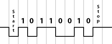
If you transmitted the character ‘M’ and looked at it on an oscilloscope, this is what you’d see. While the UART is inactive, it keeps the pin at a high state. Thus, the start bit is low so you can detect the start of a transmission. After the stop bit, if there is no more data to be sent, the pin stays high until the next start bit begins.
Hopefully this diagram makes sense. You’ll see that the bits are in reverse order because they are sent least-significant first. The horizontal unit on this diagram is time; the vertical lines are each about 8.7 microseconds apart, assuming the baud rate is set to 115200. I got that by calculating the reciprocal of the bit rate. If the bit rate is 115,200 bits per second, then there are (1/115200) seconds per bit.
The receiver looks for this pattern and interprets the bits between the start and stop bit. That’s really all there is to it! UARTs were very common on computers of the past generations. Earlier computers used a separate chip just for the UARTs, like the 8250 or the 16550A. In fact, many UARTs to this day remain software-compatible with the 16550A. Later on, computers began including a Super I/O chip with integrated 16550A-compatible UARTs.
How to use them
In microcontrollers, you typically find a UART (or multiple UARTs) available as memory-mapped peripherals. Sometimes they use the same interface as the 16550A, and sometimes not. For simplicity I’m going to talk about an AVR’s UART in this lesson instead of the 16550A. The 16550A is complicated because it has a couple of built-in 16-byte FIFO buffers for transmitting and receiving along with a fairly strange interrupt setup because of the FIFOs. The FIFOs are important for normal desktop computers because if your computer had to deal with an interrupt on every character, it would get bogged down handling the interrupts. The FIFO allows interrupts to occur less frequently. On a simple microcontroller like an AVR, handling an interrupt on every character is not a huge problem. Because of the lack of a FIFO, the AVR’s software interface will be easier to understand, which makes it appropriate for this introductory lesson.
I’m going to be using the AT90USB646 as an example. This is the same processor that I use on my Mac ROM SIMM programmer. It has a single USART. Notice the extra S? USART stands for Universal Synchronous/Asynchronous Receiver/Transmitter. It just adds the ability to work in a synchronous mode with an external clock pin. For our purposes, we won’t worry about this. We’ll be using it in asynchronous mode.
The AT90USB646 reference manual says that this chip has a single USART, described in chapter 18. It provides some sample code in both assembly and C for talking to the UART. It’s really not that hard to do.
Setting the baud rate
The baud rate is set with two registers: UBRR1L and UBRR1H. They are the low and high bytes of the full register UBRR1 (which you can also access directly as a 16-bit word, at least in AVR-GCC and AVR Libc). The equation, as per the datasheet, is:
UBRR1 = (oscillator_frequency / (16*baud_rate)) – 1;
So let’s use my SIMM programmer board as an example. It has a 16 MHz crystal, and let’s pretend we’re going for a baud rate of 9600. Thus, I should do:
UBRR1 = (16000000UL / (16*9600UL)) - 1;
Note that I used UL at the end of these constants to ensure they’re being treated as unsigned long integers. Otherwise, the intermediate calculations might get messed up due to only being promoted to 16-bit values. Your development environment will probably provide a define for the clock rate. Plus, it’s usually a good idea to create a #define for your baud rate instead of hardcoding a 9600UL randomly in the code. So it’s actually better to do this:
#define MY_BAUD_RATE 9600UL
UBRR1 = (F_CPU / (16*MY_BAUD_RATE)) - 1;
If you do the math (and integer truncation) yourself, you will discover that this will assign UBRR1 a final value of 103. Mathematically, it would be 103.166666666…, but it will get truncated down to an integer. This also means the baud rate won’t be exactly 9600 baud. If we solve the equation above for baud_rate and put our calculated/truncated UBRR1 value of 103 back in, you’ll see that we don’t get exactly 9600 baud:
baud_rate = oscillator_frequency / (16*(UBRR1 + 1));
baud_rate = 16000000 / (16*(103 + 1));
This gives us a baud rate of 9615. The AVR will actually be transmitting and receiving at 9615 baud. That’s an error of about 0.16%, which is definitely close enough to 9600 baud that it won’t be a problem. Usually you’re in good shape if you’re within a percent or two, and we are much closer than that. Keep in mind that oscillators aren’t perfect either, so UARTs are tolerant of baud rates that aren’t exactly correct.
Configuring the framing
We have to make sure that the USART knows what type of data to send and receive. Should there be 5 data bits? 8 data bits? 1 stop bit? 2 stop bits? Parity? No parity? All of this can be configured in some of the registers in the USART. The registers are called UCSR1A, UCSR1B, and UCSR1C. UCSR is short for “USART Control and Status Register”. These registers contain bits for controlling the setup of the USART as well as some bits that signal status of the USART.
The bits that are important for us to configure in order to get basic functionality are the following:
- U2X1 bit (bit 1) of UCSR1A. This is a double-speed bit that essentially turns the constant “16” in the baud rate calculation formula above into an “8” — we should make sure it’s disabled since we assumed in the baud rate calculation we did earlier that it was in fact 16.
- RXEN1 bit (bit 4) of UCSR1B. This bit enables the receiver so we can receive incoming bytes.
- TXEN1 bit (bit 3) of UCSR1B. This bit enables the transmitter so we can send outgoing bytes.
- UCSZ12 bit (bit 2) of UCSR1B and UCSZ11, UCSZ10 bits (bits 2 and 1) of UCSR1C. These three bits combine together to determine the number of data bits (5 to 9).
- 0 –> 5 bits
- 1 –> 6 bits
- 2 –> 7 bits
- 3 –> 8 bits (what we want)
- 4, 5, 6 reserved
- 7 –> 9 bits
- UMSEL11, UMSEL10 bits (bits 7 and 6) of UCSR1C. These bits determine the mode (synchronous/asynchronous) of the USART.
- 0 –> asynchronous (what we want)
- 1 –> synchronous
- 2 –> reserved
- 3 –> master SPI (this USART is capable of being an SPI master; I have discussed SPI in the past)
- UPM11, UPM10 bits (bits 5 and 4) of UCSR1C. These bits determine the parity mode (none, even, or odd).
- USBS1 bit (bit 3) of UCSR1C. This bit determines if there is 1 stop bit or 2 stop bits.
So basically, we need to set up these three registers:
UCSR1A = 0; // Not double speed mode, disable address filtering
UCSR1B = 0x18; // Enable RX and TX, high bit of UCSZ1 = 0
UCSR1C = 0x06; // asynchronous, no parity, 1 stop bit, 8 data bits
AVR Libc has some nice macros for the various bit names, so you can also do this with the symbolic names:
UCSR1A = 0;
UCSR1B = (1 << RXEN1) | (1 << TXEN1);
UCSR1C = (3 << UCSZ10);
Transmitting data
After you have configured the USART correctly, it’s very easy to send and receive. To send data, you simply write the character you wish to send into the UDR1 register. Here’s an example of transmitting the character ‘A’:
UDR1 = 'A';
You can only transmit if the hardware has finished transmitting the last character. This is because the USART does not have a transmit FIFO. Because of this, you need to check a status bit to ensure the transmitter is not already busy:
if (UCSR1A & (1 << UDRE1)) {
    UDR1 = 'A';
}
This will only transmit a character if the transmit buffer is empty. Otherwise, it won’t transmit. If you need to make sure the character is transmitted, you can wait until the bit goes high:
while (!(UCSR1A & (1 << UDRE1))) {
}
UDR1 = 'A';
So you do an empty loop until the bit goes high, after which it’s safe to write to the transmit buffer.
Receiving data
Receiving is very, very similar. First, you need to know if a character is ready to be received. The hardware will tell you if a character is waiting to be read by making a bit high in the UCSR1A register. If the bit is high, you can read the character by reading the UDR1 register:
if (UCSR1A & (1 << RXC1)) {
    received_char = UDR1;
    // do something with the received character
}
The receiver actually has a FIFO (first-in, first-out) buffer to hold a couple of received characters in case your program is unable to read the first character received before another one arrives. This is a nice little safety mechanism to have, but you still need to read received characters quickly before the small FIFO fills up. Fancier UARTs have a bigger receive buffer to enable high data rates with less processor utilization.
Example code
Here’s a sample program that will echo back any character that is received. If you type the letter ‘Z’, it will transmit the letter ‘Z’ right back to you.
#include <avr/io.h>

#define MY_BAUD_RATE 9600UL

int main(void) {
    UBRR1 = (F_CPU / (16*MY_BAUD_RATE)) - 1;
    UCSR1A = 0;
    UCSR1B = (1 << RXEN1) | (1 << TXEN1);
    UCSR1C = (3 << UCSZ10);

    while (1) {
        while (!(UCSR1A & (1 << RXC1)));
        uint8_t ch = UDR1;
        while (!(UCSR1A & (1 << UDRE1)));
        UDR1 = ch;
    }
}
It’s really not that complicated. It waits until a character is received, and then receives it. Then it waits until the transmitter is empty, and transmits the received character. Note that I put semicolons at the end of the while() loops waiting for the bits. This was done intentionally to save space over giving them an empty loop body, but it can be a little confusing to read, so I wanted to explicitly point that out.
Anyway, this whole thing is easy, right?
Interrupts
There’s a catch. If your program has to do anything other than sit in a loop waiting for a character to arrive over the UART, this whole idea starts to fall apart. If you don’t check for received data often enough, you will run the risk of losing received characters. This could happen if the receive FIFO is filled before you get around to checking the UART again. How do we solve this dilemma?
You may have been wondering why I mentioned circular buffers at the beginning of this post. What do circular buffers have to do with anything I have mentioned so far? Good news: you’ve finally reached the point in this post where everything will start to come together and make sense.
The solution to this problem is to handle the UART with an interrupt. Whenever a character is received, the UART will fire an interrupt. This will cause your main program to temporarily jump to an interrupt handler which reads the received character from the UDR1 register and stores it in a circular buffer. Somewhere in the main loop, you can occasionally check the circular buffer to see if it contains any characters and process them. As long as the buffer is big enough so that you will check it before it fills up, it will solve the problem.
On the other end, you can also create a separate circular buffer for transmitting over the UART. This will allow you to put the data into the circular buffer and then move on to other places in your program while the data is sent in the background by your interrupt handler. Basically, it prevents you from having to sit in a loop and wait for all of your characters to be transmitted before you can move onto other tasks.
This a perfect application for a circular buffer. It’s easy to make a circular buffer interrupt-safe as long as you insert from the main loop and remove from the interrupt handler (or vice versa), and inserting and removing from it are both O(1) operations. This is exactly what we need for both the transmitting and receiving end of things.
The AVR’s USART is really handy because it has what’s known as the UDRE interrupt, which stands for USART data register empty. This interrupt fires anytime the transmit data register is ready for you to write another character. It’s based on the same status bit we checked in the non-interrupt-driven code above. So if the USART is idle, this interrupt will fire. Because of this interrupt, there are no special cases when you first start transmitting characters. When you put a character in the TX buffer, you have to ensure that the UDRE interrupt is enabled. In your UDRE interrupt handler, if the TX buffer is empty, you disable the UDRE interrupt. This logic is very simple compared to other UARTs, which often require special cases when you transmit your first character in order to get the interrupts rolling.
Example code
Here’s some sample code I wrote for interrupt-driven UART functionality. It consists of a header file and source file for the UART driver. You will notice the ring buffer functions which I renamed and borrowed from my post about ring buffers. Many AVR microcontrollers have multiple USARTs. This particular one works with USART1 on the AT90USB646.
uart.h:
#ifndef UART_H_
#define UART_H_

#include <stdbool.h>
#include <stdint.h>

void uart_init(uint32_t baud);
void uart_write_char(char data);
char uart_read_char(void);
bool uart_rx_buffer_empty(void);
bool uart_tx_buffer_empty(void);
bool uart_rx_buffer_full(void);
bool uart_tx_buffer_full(void);

#endif /* UART_H_ */
uart.c:
#include "uart.h"
#include <avr/io.h>
#include <avr/interrupt.h>

#define RING_SIZE   128
typedef uint8_t ring_pos_t;

static volatile ring_pos_t tx_ring_head;
static volatile ring_pos_t tx_ring_tail;
static volatile char tx_ring_data[RING_SIZE];

static volatile ring_pos_t rx_ring_head;
static volatile ring_pos_t rx_ring_tail;
static volatile char rx_ring_data[RING_SIZE];

static int tx_ring_add(char c);
static int tx_ring_remove(void);
static int rx_ring_add(char c);
static int rx_ring_remove(void);

void uart_init(uint32_t baud) {
    // TODO: if you are OK with hardcoding the bit rate,
    // consider using avr-libc's <util/setbaud.h>
    // functionality instead.

    // Set baud rate
    UBRR1 = (F_CPU / (16*baud)) - 1;
    // Enable RX and TX, turn on RX interrupt,
    // turn off data register empty interrupt until needed
    UCSR1B = (1 << RXEN1) | (1 << TXEN1) | (1 << RXCIE1);
    // 8 data bits, 1 stop bit
    UCSR1C = (3 << UCSZ10);

    // Clear out head and tail just in case
    tx_ring_head = 0;
    rx_ring_head = 0;
    tx_ring_tail = 0;
    rx_ring_tail = 0;
}

void uart_write_char(char data) {
    // Wait until there's room in the ring buffer
    while (uart_tx_buffer_full());

    // Add the data to the ring buffer now that there's room
    tx_ring_add(data);

    // Ensure the data register empty interrupt is turned on
    // (it gets turned off automatically when the UART is idle)
    UCSR1B |= (1 << UDRIE1);
}

char uart_read_char(void) {
    // Wait until a character is available to read
    while (uart_rx_buffer_empty());

    // Then return the character
    return (char)rx_ring_remove();
}

bool uart_rx_buffer_empty(void) {
    // If the head and tail are equal, the buffer is empty.
    return (rx_ring_head == rx_ring_tail);
}

bool uart_tx_buffer_empty(void) {
    // If the head and tail are equal, the buffer is empty.
    return (tx_ring_head == tx_ring_tail);
}

bool uart_rx_buffer_full(void) {
    // If the head is one slot behind the tail, the buffer is full.
    return ((rx_ring_head + 1) % RING_SIZE) == rx_ring_tail;
}

bool uart_tx_buffer_full(void) {
    // If the head is one slot behind the tail, the buffer is full.
    return ((tx_ring_head + 1) % RING_SIZE) == tx_ring_tail;
}

static int tx_ring_add(char c) {
    ring_pos_t next_head = (tx_ring_head + 1) % RING_SIZE;
    if (next_head != tx_ring_tail) {
        /* there is room */
        tx_ring_data[tx_ring_head] = c;
        tx_ring_head = next_head;
        return 0;
    } else {
        /* no room left in the buffer */
        return -1;
    }
}

static int tx_ring_remove(void) {
    if (tx_ring_head != tx_ring_tail) {
        int c = tx_ring_data[tx_ring_tail];
        tx_ring_tail = (tx_ring_tail + 1) % RING_SIZE;
        return c;
    } else {
        return -1;
    }
}

static int rx_ring_add(char c) {
    ring_pos_t next_head = (rx_ring_head + 1) % RING_SIZE;
    if (next_head != rx_ring_tail) {
        /* there is room */
        rx_ring_data[rx_ring_head] = c;
        rx_ring_head = next_head;
        return 0;
    } else {
        /* no room left in the buffer */
        return -1;
    }
}

static int rx_ring_remove(void) {
    if (rx_ring_head != rx_ring_tail) {
        int c = rx_ring_data[rx_ring_tail];
        rx_ring_tail = (rx_ring_tail + 1) % RING_SIZE;
        return c;
    } else {
        return -1;
    }
}

ISR(USART1_RX_vect) {
    char data = UDR1;
    rx_ring_add(data);
}

ISR(USART1_UDRE_vect) {
    if (!uart_tx_buffer_empty()) {
        // Send the next character if we have one to send
        UDR1 = (char)tx_ring_remove();
    } else {
        // Turn off the data register empty interrupt if
        // we have nothing left to send
        UCSR1B &= ~(1 << UDRIE1);
    }
}
Finally, here’s a test program that tests out the USART:
#include <avr/interrupt.h>
#include "uart.h"

int main(void) {
    cli(); // disable interrupts
    uart_init(9600);
    sei(); // enable interrupts
    while (1) {
        uart_write_char(uart_read_char());
    }
}
This particular sample program doesn’t really take advantage of the fact that the code is interrupt-driven, but at least it tests the code out. The interrupt-driven aspect of the code shines when you need to send a 50-byte string and don’t want to wait around until it finishes sending. With this code, if you quickly write 50 bytes, the program will continue doing other things while the 50 bytes are sent in the background as interrupts come in. For receiving, you can let your program do many things without worrying about losing a received character. Every time through your main loop, you should process all characters that are waiting in the receive buffer to ensure that it doesn’t fill up.
Other functions
You could easily add other functions for transmitting a string, receiving a full line, etc. It would probably be nice for the transmit and receive functions to have optional parameters to tell them not to block if the buffers aren’t ready. These are all excellent exercises I leave to you, the reader, to implement.
Conclusion
I hope this explains the UART/USART in enough detail to get you started. This is a very important peripheral that is commonly used for interfacing with displays, sensors, and other microcontrollers. If you’re going to use a UART/USART, I would highly recommend that you do it with interrupts as I described above. This is definitely the type of thing you should stick into your toolbox of peripheral drivers and reuse on all of your projects.


What a great tutorial! Helped me a lot with my project!
Thank You and keep up the good work! 🙂