Several months ago, Will from CayMac Vintage reached out to me looking to resurrect my old Mac ROM SIMM programmer project. As a quick summary of that project, it provides a convenient way to program custom 64-pin ROM SIMM modules for vintage Macs from the late ’80s to early ’90s. There are several reasons you might want to do this, including: replacing an original ROM module that has gone bad, disabling the startup RAM test to decrease boot time in systems with a lot of RAM, bbraun’s amazing bootable ROM disk hack, or my startup chime hack. JDW recently made a cool YouTube video explaining custom ROM SIMMs if you’re curious about them. He even included some footage from 2003 of me playing basketball!
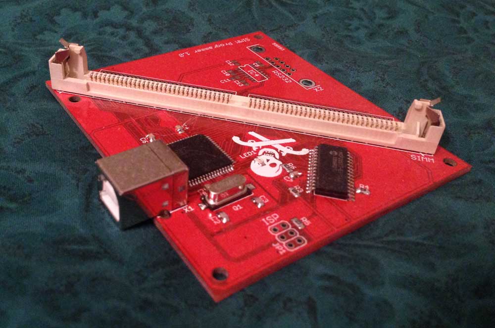
I used to make programmer boards and programmable ROM SIMMs and sell them to hobbyists, but it burnt me out. In particular, assembling the boards and the logistics of shipping were not fun to deal with. Thankfully, in 2016, Steve from Big Mess o’ Wires stepped in to take over. He made his own customizations to the programmer and made some really neat improvements to the bootable ROM disk driver. He still sells the Mac ROM-inator II SIMM to this day, but he stopped selling the programmer board. In the meantime, many other players have entered the market with custom ROM SIMMs, but nobody has been making the programmer available to the community, likely due to my non-commercial license on the PCB design.
Will was looking to fill that void. I helped him get going, but we discovered that the AT90USB646 microcontroller that I originally used was hard to find due to the chip shortage. At the time, it was easier to find the AT90USB1286 instead, which is essentially just the exact same chip, but with 128 KB of flash instead of 64 KB of flash.
Long story short, I was able to get the firmware working with the AT90USB1286, but it was more difficult than I thought it would be. For some strange reason, the 646 and 1286 have a subtle difference other than the flash size: the USB PLL bits have different meanings. Debugging this remotely without hardware of my own was “fun” to say the least, but I got it working! (Will offered to send me one, which was very kind, but I declined and later built my own.) I was able to automatically detect the chip type at runtime so that the same firmware binary could be used on both variants.
I also had to make a different bootloader binary for the 1286 because AVRs store their bootloader at the top of flash, which is a different location between the 646 and 1286. Having a separate bootloader wasn’t a big deal though. That’s just a one-time thing burned onto the chip when building the programmer. The main trouble I ran into with the bootloader was remotely debugging two separate (and simultaneous) problems involving incompatibility with the upper 64 KB of flash: LUFA doesn’t like having the USB descriptors in the upper flash and at least some versions of AVR-GCC have a switch/case jump table issue with the upper flash. It’s unclear to me whether the latter problem has actually been fixed in newer versions of AVR-GCC, but the AVR Libc user manual still refers to the issue as of this writing:
NOTE: The tablejump instructions use the LPM assembler instruction for access to jump tables. Always use -fno-jump-tables switch, if compiling a bootloader for devices with more than 64 KB of code memory.
Anyway, you may have gathered from the title that getting the code running on the AT90USB1286 isn’t the main topic of this post. That was just enough background info to introduce the story and give a glimpse into my mind at the time. During the process of getting the 1286 chip working, I came to several realizations:
- I dislike programming for AVRs. Don’t get me wrong, they were nice in their day, but they require the use of silly quirks when writing C code (e.g. PROGMEM) due to being 8-bit and having separate program and data address spaces. The bootloader issues I ran into with the upper 64 KB of flash were particularly frustrating. It’s 2023. Why should I be dealing with stupid problems like that?
- AVRs are quite expensive for what they provide. On the other hand, their longevity is great! But is that worth the cost?
- The use of the AVR also required me to use an MCP23S17 SPI I/O expander because there weren’t enough I/O pins to wire up to the entire SIMM socket. This added unnecessary cost to the programmer while simultaneously slowing it down.
If you put all of these together, I was adding to the cost of the programmer just for the privilege of using an 8-bit architecture that I hate working with. That’s insanity! Although, I will admit that the longevity of the chip has been very nice. There were two main reasons I originally picked AVR: I was already familiar with the architecture, and it was able to run at 5V. The 5V requirement is important because old Mac ROM SIMMs operate at 5V. I didn’t want to deal with level shifters.
This got me thinking: how hard would it be to port the programmer to a new architecture? I was pretty sure I could drastically speed up programming time by using a faster processor without an I/O expander, especially if the data and address pins could be wired efficiently to full I/O ports that wouldn’t require special bit manipulation to read and write. I mustered up enough motivation in my spare time to search for something a little newer that I might be able to port the firmware to. I looked on Digi-Key for microcontrollers that are 32-bit, can run at 5V, have at least 57 I/O pins, and can be a USB device. They also needed to be in stock.
The two least expensive parts fitting the criteria were the Renesas R5F52315AGFP#30 ($4.40480 in quantities of 25) and the Nuvoton M258KE3AE ($4.386 in quantities of 25). The Renesas chip is part of their RX231 family that uses the Renesas RXv2 CPU core, whereas the Nuvoton chip is an ARM Cortex-M23.
In comparison, the AT90USB646 is $7.54 in quantities of 25 (the 1286 is even more expensive), plus the I/O expander adds extra cost and assembly time.
I was intrigued by the Nuvoton microcontroller. It’s ARM, which I’m very comfortable with. It runs at 48 MHz, has 16 KB of RAM, and 128 KB of flash. It is also advertised as having crystal-less USB 2.0 full-speed operation, meaning the PCB wouldn’t even need a crystal. This translates to even more cost savings, although very minute.
Really? Nuvoton? I thought they only made Super I/O chips for computer motherboards. I had no idea they were in the microcontroller business. Availability was a bit of a concern with less than 200 in stock at Digi-Key, but it would be possible to order more if needed. I asked a few questions to Nuvoton about 5V compatibility and they were responsive. I was impressed! I went forward with testing it out.
I ordered a NuMaker-M258KE dev board. This is a pretty simple board that has the M258KE3AE and brings out all of its pins to headers. It also comes with a segment LCD, but I didn’t care about that. One really cool thing about this board is it also has a Nu-Link2-Me programmer integrated, which you can snap off and use as a production programmer for your own boards. After a shipping snafu where my order was accidentally sent to Thailand, it finally arrived and I started playing with it.
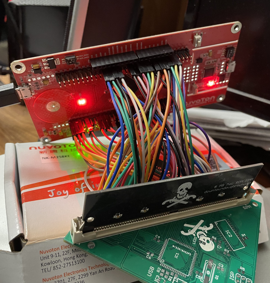
I ran some of Nuvoton’s sample projects and got my own “Hello World” program running on the board to prove I could write code for it. As soon as I was confident enough, I began the process of porting over the SIMM programmer firmware. First, I soldered a zillion (well, more than 60) jumper wires to a blank SIMM programmer board so I could hook it up to the dev board:
Then I painstakingly assigned where I wanted pins to go on the chip and hooked them up one by one to the dev board. This resulted in a final monstrosity that I named the “Small Mess o’ Wires” as an homage to BMOW.
In 2020 I had already broken the code out into a hardware abstraction layer, so the AVR-specific code was all living in the “hal/at90usb646” directory. Well, except for one function I accidentally missed, but that was an easy fix. Theoretically, all that would need to be done was reimplementing everything in that directory, but in a way compatible with the Nuvoton microcontroller instead.
Hardware abstraction layers don’t have to be fancy. They don’t even need to add any runtime overhead. If you’re concerned about the overhead of adding an intermediate function call, create a static inline function in an implementation-specific header file instead. If you can’t split up the implementation-specific and generic portions of a module in a way that still maintains its performance, just repeat the generic stuff in each implementation of the module. I promise I won’t tell the code police! Software development is an art and there’s not necessarily a universally correct way to accomplish something.
I imported Nuvoton’s CMSIS core code and peripheral header files and tweaked them as needed. Isn’t CMSIS great? It at least makes things kind of standard between ARM implementations. Then, I reimplemented everything piece by piece and got to the point that it would compile.
- SPI driver (stubbed out because the I/O expander wasn’t needed anymore)
- GPIO
- The Nuvoton chip also has pulldown resistors, so I was also able to add detection of shorts to +5V to my electrical test functionality, which is something I couldn’t detect on the AVR. I can’t stress how useful this electrical test functionality has been ever since I first developed it in 2011! It instantly tells you where your soldering mistake is if you accidentally short two pins together when building a SIMM or programmer.
- ParallelBus — my implementation for bit-banging a 32-bit parallel data bus that can do read and write cycles with 21 address pins and /CS, /OE, and /WE signals, for interacting with the attached ROM SIMM (up to 8 MB in size)
- This reimplements a lot of GPIO functionality with direct register accesses rather than going through my GPIO driver, but it’s a necessary evil for efficiency.
- Miscellaneous hardware initialization, delay functions, entering bootloader, etc.
- Nuvoton’s USB device code
- I tried to make my own drivers from scratch for most of these things, just relying on Nuvoton’s struct definitions for register accesses to each peripheral. In general this was a good approach for efficiency and a better understanding of the hardware, but USB is too complicated to redo from scratch so I reused their USB code, although I did modify it a bit in subsequent commits.
The next point I want to make is that USB isn’t hard, or at least shouldn’t be hard in theory. Just start from an example from your vendor that is close to what you need and adapt it as necessary. Or use a stack such as TinyUSB. In my case, I was happy with Nuvoton’s supplied code so I didn’t need to go any further. I did have to rearrange things a little bit, but it turned out great. I will admit that if your vendor has crappy sample code and it’s not supported by a better USB stack, you might have a tougher time here.
Because the code had already been ported to be in a HAL, I also had a template to follow for the build system. I used CMake, so I just had to create a few CMake files to indicate the correct source files, compiler flags, and linker options.
I would be lying if I said I got it all finished at once. I tested everything piece by piece. I think I got USB working first just because it actually gave me a communication path to my PC in order to test everything else through the existing SIMM Programmer control software.
Amazingly, this process all went very smoothly over the course of a few days. USB was the hardest piece to get working, but it still wasn’t that hard. I didn’t even make any mistakes when wiring up the pin headers to the dev board. As soon as I had all of the drivers implemented and lightly tested, I attempted to program a SIMM and the whole thing worked great on the first try. It was noticeably faster than the AVR-based version. In fact, I was worried it might be too fast — more on that later.
I also used this new revision of the programmer as an opportunity to fix a dumb design decision I made back in 2012 with the original AVR-based programmer. Back then, I knew I wanted the programmer to be “unbrickable” even if someone flashed a bad firmware file to it. That was a good idea, but I implemented it in a weird way due to lack of available GPIO pins: I coded my original AVR bootloader to enumerate as a USB device and wait until it received a command from the programmer software before jumping to the actual firmware. This guaranteed you would always be able to reflash the main firmware. It worked fine, but it resulted in an annoying slowdown because the first time you actually wanted to use it, it would have to disconnect itself as a USB device, wait a moment for things to settle, boot the main firmware, and reconnect as a USB device. Furthermore, if you were constantly having to power cycle it while testing a concept with your custom ROM hacking, every time it power cycled it had to repeat this slow bootloader -> firmware re-entry process. It was a huge time waster during normal operation. On this new implementation I opted to add a “bootloader entry” header. The bootloader will always just immediately enter the main firmware at startup, unless you short the bootloader entry pin to ground with a paperclip or something like that. Another benefit of having extra GPIO pins available!
To be honest, I could probably port this logic over to the AVR-based version too. It would require using one of the pins I reserved for the RS-232 port I didn’t populate. If anyone has an AVR-based ROM SIMM programmer, is capable of flashing their own bootloader, and wants this change to speed up normal operation, let me know and I’ll whip up a bootloader binary for you.
Speaking of the bootloader, it was also pretty easy to port to the new architecture. The M258KE processor has an extra 4 KB chunk of flash memory called LDROM. It’s designed to store a small bootloader. You can set config bits similar to the AVR’s fuse bits to tell the chip to boot to the LDROM instead of the main flash, which is known as APROM. 4 KB isn’t much space, but I was able to pare down Nuvoton’s startup code and USB sample code in order to get everything small enough to fit. There was one special USB byte-by-byte memory copy function in particular that was being inlined all over the place, and simply making it not inline saved a ton of space. Even if I hadn’t been able to make everything fit, I could have used a portion of the normal flash memory for my bootloader instead. But I wanted to use the LDROM if I could, and I ended up succeeding.
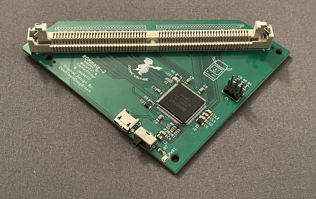
Now that I had completely tested the concept, it was time to make a new board. This time around, though, I didn’t do the actual board design. I didn’t have time even if I wanted to. The CayMac team — Joakim in particular — did all of the board design. I just provided some constraints about how to arrange the data and address pins to make the software faster. For maximum efficiency, I wanted two full 16-bit ports to be used for the 32-bit data bus so that the firmware wouldn’t have to manipulate the data before writing it out to the ports. I also wanted the address bus to be arranged similarly to minimize bit manipulation.
Less than a month later, Will and Joakim had boards in their hands and I was able to send them a new build of my ARM firmware port. I simply had to move the pin mappings around to match their final board design. It all worked great, and they also noticed the massive speed improvement! There was just one minor hiccup with accidentally swapping USB D+ and D- in the pinout.
After I got one of the new boards, I did some final testing to make sure that I wasn’t accessing the flash chips too quickly. After all, they have timing requirements that must be met. Each flash chip’s timing requirements are a little different, but as long as I’m not going too fast for the slowest chip everything should be fine.
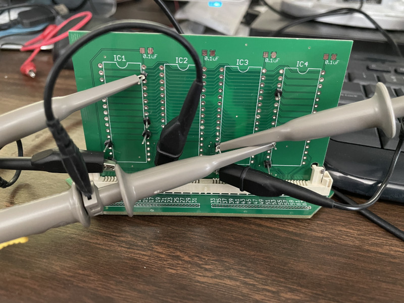
Using an old crazy DIP ROM SIMM PCB I designed years and years ago, I probed various pins and timed all of the operations — in particular the read and write cycles. It quickly became apparent that I wasn’t even close to being too fast, even with this faster microcontroller. Here’s an example of what write cycles look like. I set the address, then the data, and then I do a quick negative pulse on /WE to perform the write.
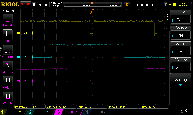
Even though I immediately drive /WE high after driving it low, it stays low for about 100 nanoseconds or so. I needed for it to be at least 40 ns, so no problems there. The other timing requirements between transitions were in the ballpark of 40-70 ns, and as you can see from this scope trace I’m nowhere near that.
This does mean it’s likely possible to optimize the performance even further if I really sit down and think about how to make better use of the CPU during these write cycles. But honestly, it’s already pretty darn fast as it is. Much faster than the old AVR-based version.
The awesome part about this firmware port is that from the perspective of the SIMM Programmer software, nothing changed at all. It talks to it exactly the same way as it talks to an old programmer. It just happens to be faster. So it’s a nice case study on a pretty much seamless transition of a project from one architecture to another. Going forward, as long as I don’t hit limitations of code space on the AVR, I should be able to keep both the AVR and ARM versions at 100% feature parity — except for detecting +5V shorts in the electrical test, which I can’t do with the AVR. The only real difference between the two versions is that under the hood during firmware updates, I have to upload a different firmware binary depending on what revision of the board I detect.
That leads me to the final major topic I wanted to talk about — simplifying the firmware update process. While porting the firmware to the Nuvoton microcontroller, I wanted to make sure I had the ability to identify whether a programmer is AVR-based or ARM-based. The simplest way to do this was to use the bcdDevice field of the USB device descriptor. The old programmer was revision 0001 and the new programmer is now revision 0002. Operating systems all provide easy access to this info, so this makes it simple for the Mac/Windows/Linux control software to know what programmer revision it’s talking to. I did have to modify QextSerialPort to give me access to the bcdDevice field though.
I wish I had thought about the possibility of multiple revisions/architectures of the programmer board from the start, because then I could have added a header to the firmware update file and all versions of the control software could have been prepared to know whether a particular firmware binary was meant for a particular version of the board. I was still able to add some smarts though. SIMM Programmer 2.0 knows what version of the board is attached, and inspects the supplied firmware update file to make sure the bcdDevice field in the USB device descriptor embedded in the firmware file matches the connected programmer. Additionally, I created a new firmware update format that contains the firmware for both variants simultaneously.
The end result is that as long as version 2.0 or later of the control software is being used, the user won’t even need to care about what kind of programmer they have. If they supply my single “old + new” combined firmware update file during a firmware update, it will automatically figure out which firmware matches the board they have and reflash the correct firmware blob. If they use an older pre-2.0 version of the control software, it will dumbly upload the entire combined firmware file. I designed the new update file format so that the start of the file is the old AVR firmware, so that should work fine too, as long as they have an older AVR-based programmer. The only hole in this update scheme is if someone downloads a pre-2.0 version of the control software and uses it to update the firmware of an ARM revision of the programmer, the whole file will be flashed which is effectively the AVR firmware with the ARM version appended to it. But it won’t brick the board — it just won’t work correctly until they update the firmware using version 2.0 or later of the control software. I don’t think that will happen in practice though. People who obtain a brand new ARM revision of the programmer will be downloading the latest version of the control software, so I think it all works out in the end. I could have avoided that small caveat by thinking ahead when I first designed the firmware update capability over 10 years ago, but I don’t think it really matters.
Oh, and one last note: having a HAL in your firmware is great, even if you don’t think you need it. Even if you never plan on ever porting your code to a new architecture, I think you should do it. Why? Because you could write a simulator to run your firmware on your PC. I actually did this with the SIMM Programmer. I can simulate an attached USB device using Linux’s dummy_hcd module to create a fake serial port gadget with the proper USB vendor and product ID. Then my PC can run the actual firmware built from the same codebase as the AVR and ARM versions, but compiled for x86_64 instead. It’s still a work in progress, but if I finish it, it will be useful for testing compatibility with NOR flash chips that I don’t have on a physical SIMM by simulating them. I might do a blog post about running embedded firmware on PC in general in the future. Being able to build and run your firmware on PC is a fantastic way to test and verify your code. It also has the potential to make debugging much easier, as long as the bug you’re tracking down isn’t part of the hardware-specific code.
And that’s the story of how I seamlessly ported my old AVR-based project to ARM! I’m really happy with how it turned out. It programs SIMMs so much faster and it feels good to have finally moved it to a modern architecture. The new version of the programmer is known as the CayMac ROMmate-2 and is available to buy today.


[…] Doug Brown ☛ Porting my Mac ROM SIMM programmer from AVR to ARM […]