TL;DR: The pinout of modern programmable Mac ROM SIMMs needs to be changed for correct operation in Quadras. If you’re interested in how I reached that conclusion, or at least want to see some cool pictures, read on below.
If you’ve been paying attention to the Classic Mac scene these days, you’re probably familiar with custom Mac ROM SIMMs such as the ROM-inator II. If not, here’s some intro material about them. JDW also made an awesome YouTube video explaining them.
One thing that you usually discover when searching for info about these programmable ROM modules is that they’re compatible with the earliest 68030-based desktop Macs: the SE/30, IIx, IIcx, IIci, IIfx, and IIsi. The most common use of them is to set up a special custom bootable ROM disk using Rob Braun’s driver, Big Mess o’ Wires’ driver based on Rob’s, or Garrett’s Workshop’s driver. In general, the compatible ROM images out there are all using the IIsi ROM which is capable of booting any of the aforementioned Macs.
What you may not know is that most of the later 68k Macs also have provisions for a ROM SIMM socket, but aside from the very first Quadras (700/900/950) which always have the socket installed, it’s not usually populated. Some early production or prototype units have it, but most just have empty through-holes filled with solder where the socket would go.
Up to this point, a few people have tinkered with custom ROMs on Quadras. Rob Braun figured out how to enable massive amounts of RAM in the Quadra 610/650/800 by reconfiguring the memory controller to recognize larger SIMMs, cy384 has played with overclocking the 650, and Cameron Kaiser hacked the Apple Interactive Television Box ROM. I’ve never really put much thought into these later models due to the fact that most of their logic boards don’t have the socket populated, but Will and Joakim from CayMac Vintage have been experimenting with how to make use of the SIMM socket if you solder it in yourself, which is easier said than done. Joakim, with a tiny bit of help from me, figured out how to use the full 8 MB of ROM space on several of the models including the Quadra 700/900/950 and LC/Quadra 475, and ported Rob’s ROM disk driver to it.
However, it hasn’t entirely been smooth sailing. Joakim discovered that until he manually disabled the onboard ROM chips by lifting a pin, the LC 475 wouldn’t boot with a customized programmable SIMM installed. It played the infamous chimes of death instead. I happen to have an LC 475 here as well, and I did some research to figure out what was going on. I started by looking at pictures and known pinouts of Apple’s ROM SIMMs. As I looked at the SIMMs, I focused on the /CS (chip select) and /OE (output enable) signals. Those are the two signals relevant to deciding whether a ROM or flash chip is outputting data. They both have to be low in order for data to be output.
Let’s start with Apple’s stock ROMs that everyone bases their programmable SIMM pinouts on. What better way to inspect the pinout than with an X-ray image? You can see in Thom‘s incredible X-ray image of a stock IIsi ROM SIMM that there are traces going between the SIMM edge connector and the ROM chips for both pins 11 (/CS) and 12 (/OE) of the SIMM:
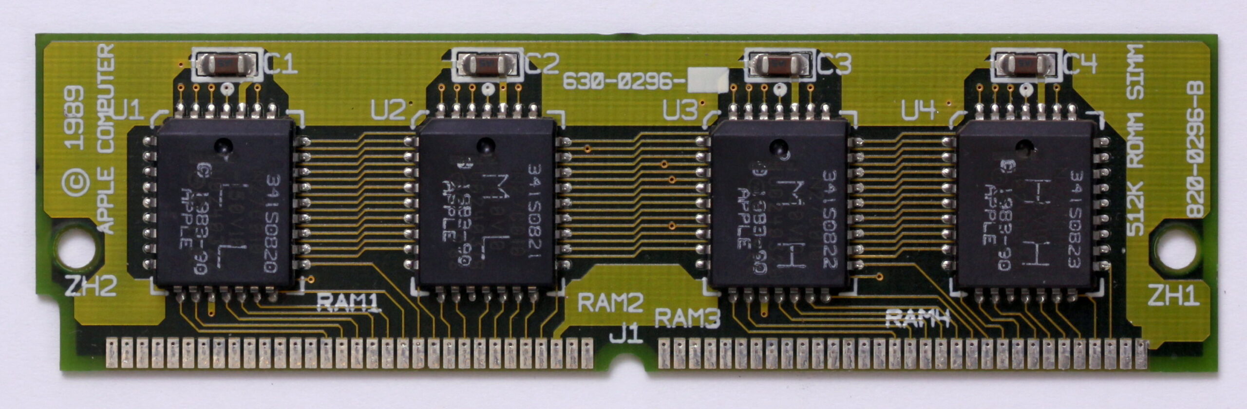
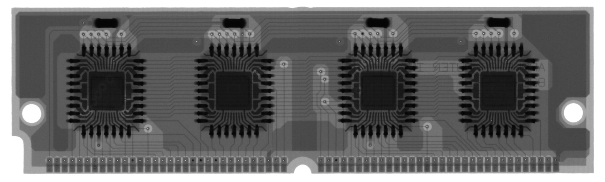
I know an X-ray picture is overkill for determining pinouts for this, but it was too cool to not show in the blog. Thanks for giving me permission to share this picture, Thom!
You can also see that pin 13 is connected to an internal layer. This layer happens to be +5V. Apple says that pin 13 is one of several +5V pins in the pinout, but I repurposed it as /WE (write enable) when I designed my programmable SIMMs and programmer in order to ensure /WE would be held deasserted when inserted in the Mac. After all, it’s right next to /CS and /OE. It just makes sense. The other SIMM vendors have followed suit in order to ensure compatibility with my programmer board.
One last note on this picture to keep in mind going forward: you can see that pins 2 and 3 are not connected to anything, not even an inner layer. Those pins are referred to as A0 and A1 in Apple’s pinout, and they are even hooked up to the address bus on several II-series logic boards, but they aren’t useful because the SIMM supplies 4 bytes of data at a time. Regardless of what A0 and A1 are asking for, the data will be correct based on all of the higher address lines starting with A2.
Now that we’ve seen how the /CS and /OE signals are simply hooked to the corresponding chip pins on ROM SIMMs for early Macs like the IIsi and SE/30, let’s look at a Quadra 840av ROM SIMM I used to own. I had no need for it, so I sold it years ago to someone who had an early logic board that didn’t have soldered ROM chips.
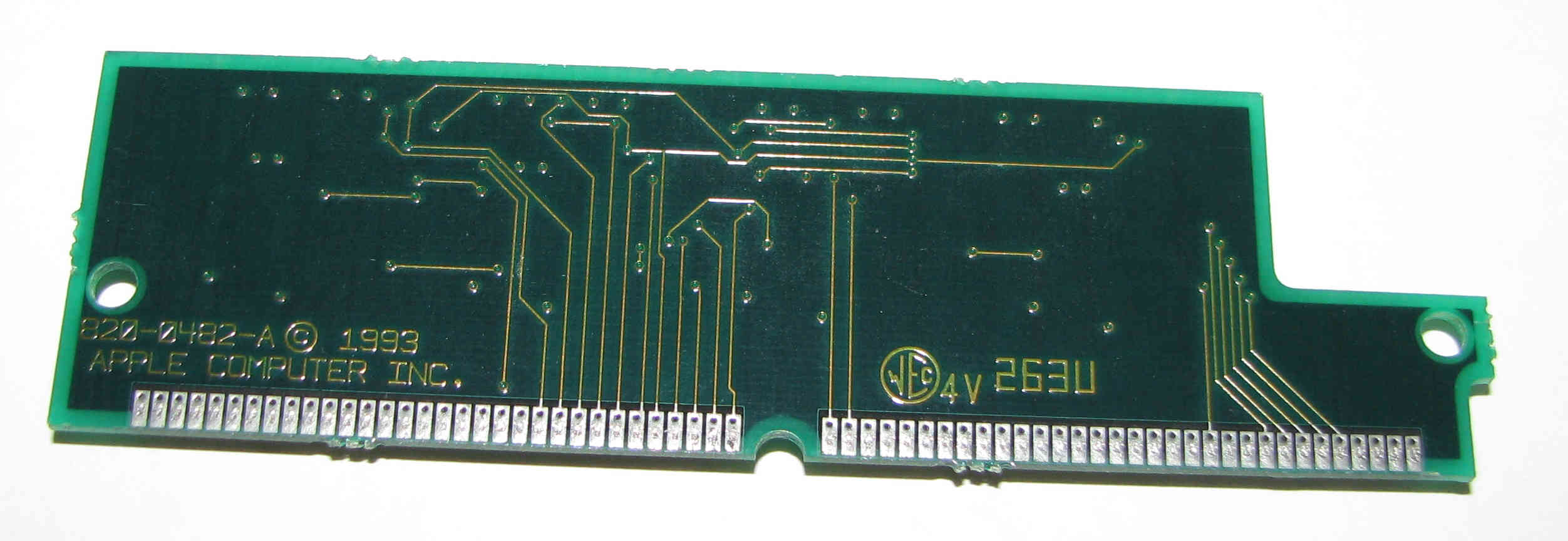
The notch cut out of this SIMM is interesting. I suspect it may be needed in the 660av, which shares the same ROM, in order to make room for the CD-ROM drive. It’s pretty cramped in there. Anyway, if you pay close attention to the traces, you will see that pin 12 (/OE) goes to the chips and pin 11 (/CS) doesn’t have any traces coming out. Fortunately, I took detailed notes when I owned this SIMM. Pin 11 is connected to the internal +5V layer, and the four chips have their /CS pins (22) tied to GND so they’re always active. That always puzzled me, but I just kind of left it as an unsolved mystery in my head. (Stay tuned: the mystery is now solved.)
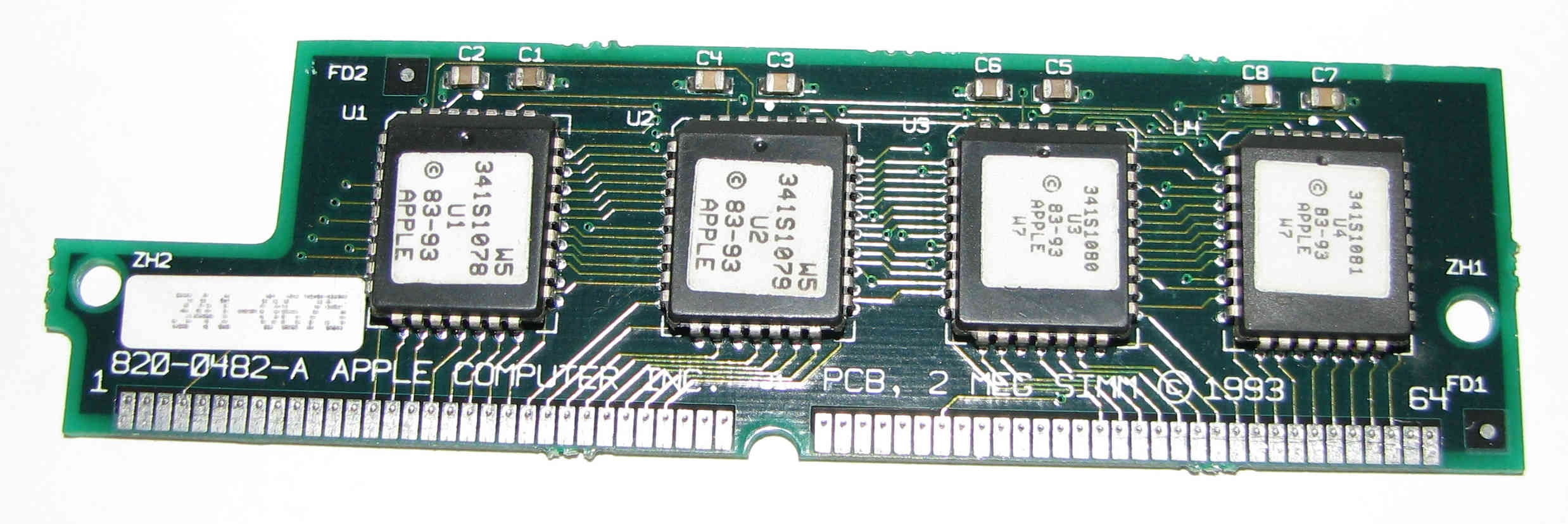
Josh Watson also kindly shared images of Apple’s programmable “Lobos” ROM SIMM from this era that he bought on eBay a couple of years ago. He gave me permission to reproduce the images in this post. Thanks, Josh!
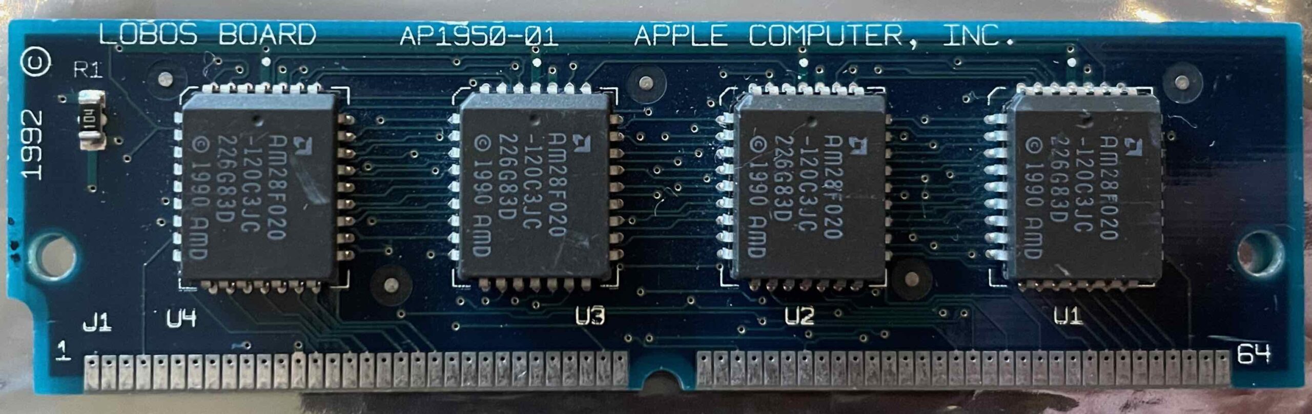
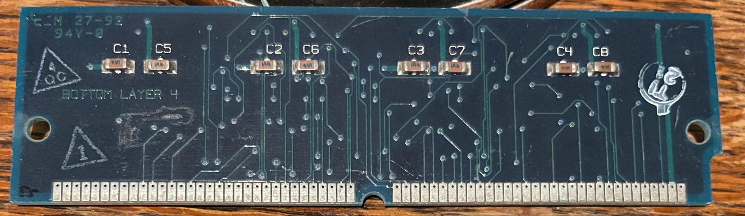
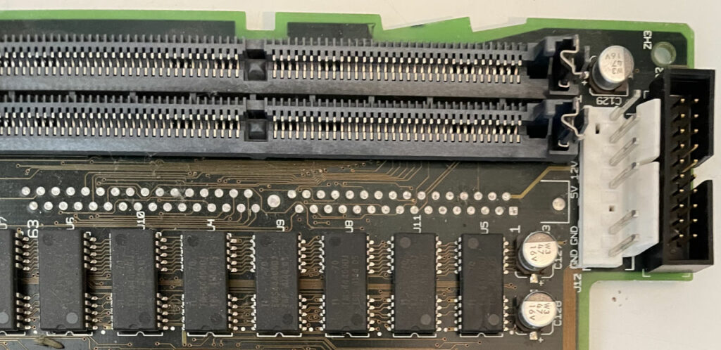
This SIMM provides some additional fascinating context. Once again, pin 12 goes to the chips and pin 11 doesn’t go anywhere. Yes, it’s a 4-layer board, so I can’t be 100% certain, but typically the inner layers are going to be ground and +5V. I’m assuming it’s tied to +5V and the chips have /CS tied to GND, just like the Quadra AV SIMM above. The interesting thing about this SIMM is that pins 2 and 3 are also being used. Pin 2 has a thick trace coming out of it which usually implies higher current. If you follow the vias, you can see that the thick trace is going to pin 1 of the chips, which is VPP — a higher voltage used when programming older flash chips. Most modern flash chips don’t need a separate VPP supply, but back then they did. My LC 475’s logic board has this pin wired directly to +12V. You can see the thick trace going to pin 2 of the SIMM socket in the image at the very top of this post.
What about pin 3? It’s pretty difficult to see in the pictures, but if you stare long enough and trace your way through the vias that are annoyingly hidden by that white stamp, you can see that it’s going to pin 31 of the chips, which is /WE. If you don’t believe me, Josh also posted a close-up view of the stamped area through a loupe at the above link.
Not that we really need any more examples at this point, but this pinout of pins 2, 3, 11, and 12 also appears to match the programmable SIMM that was used in the Apple Interactive Television Box.
Let’s take a brief moment to let that last part about pin 3 sink in: /WE actually goes to the SIMM socket? Does this mean that Quadras are capable of flashing their ROM SIMMs in-system? I really think it does. On my LC 475, pin 3 indeed has a trace coming out of it. It’s on the bottom side of the board so you can’t see it in my pictures, but using my multimeter in continuity mode along with some common sense, I was able to determine that it goes to a pin on U3, which is the MEMCjr memory controller IC. That’s exactly where I would expect it to go if the machine was capable of sending write cycles to the SIMM socket.
I don’t want to get hung up on the in-system programmability though. That’s a really cool topic, and if I am able to get it to work, it may be the subject of a future blog post. What I want to focus on in this post is why Joakim couldn’t get a modern programmable SIMM to work in the LC 475 without hacking his logic board.
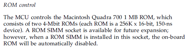
On the IIci and IIsi, you need to mess with the W1 jumper on the logic board in order to use a ROM SIMM. It tweaks the /CS or /OE signal of the onboard ROMs to force them to be disabled. On the other hand, Apple pointed out in the Quadra 700 developer note that the on-board ROM chips are automatically disabled when a ROM SIMM is inserted:
With that in mind, plus all of the info I had obtained by looking at all of these ROM SIMMs, I was suspicious about the /CS signal (pin 11 of the ROM SIMM socket). Apple clearly tweaked the usage of it in the Quadra era. I inspected it further on my LC 475’s logic board. It goes directly to the /CS pin of the onboard ROM chips. It’s also connected to ground through a 300Ω resistor (R97, on the bottom of the board). I wasn’t able to find any connections to the memory controller IC or anywhere else on the logic board. That’s the extent of the ROM /CS circuit. Here’s a diagram of everything I just described:
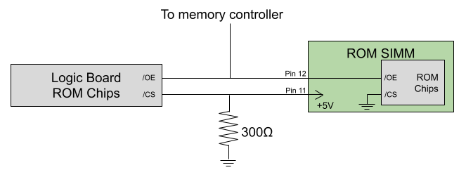
If you think about it in conjunction with the newer Apple SIMMs we looked at above, this makes perfect sense! The logic board asserts the onboard ROM chips’ /CS pins with a fairly weak pulldown resistor. If you insert a SIMM following Apple’s design, the /CS pin being tied directly to +5V overrides the pulldown and forces the logic board’s onboard chips to be disabled. Since the chips on the SIMM have their /CS pins tied to ground (asserted) instead, they are enabled and completely replace the onboard ROMs.
I was already aware that the newer models automatically disable the onboard ROM when a SIMM is inserted, but I had assumed that Apple was detecting it by using one of the existing pins that was dedicated for GND or +5V. I didn’t realize that they had repurposed pin 11 to accomplish it.
This solves a big mystery for me. I had always wondered exactly why that 840av SIMM had done it slightly differently, but I didn’t have enough background info to understand it. Now it all makes sense. I’ve confirmed that this same design is used on a bunch of different Quadra logic boards, including the 475, 575, 630, 700, 800, 840av, and 900. It’s honestly a pretty nice solution.
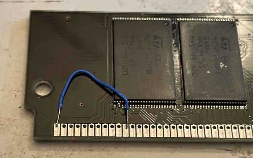
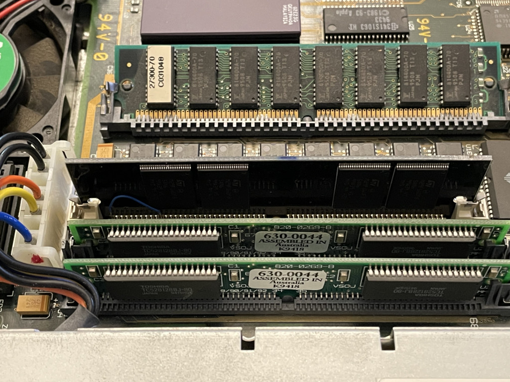
I sent this research to Joakim and he hacked a programmable 8 MB ROM SIMM that is based on my design. He cut the trace that goes between pin 11 and the chips, and then tied pin 11 to +5V and the chip side to GND. Then he resoldered the onboard ROM pins that he had lifted for testing, and inserted the hacked SIMM into the LC 475. It worked perfectly! I’ve also replicated his success in my LC 475 by installing the socket and hacking one of my own SIMMs the same way.
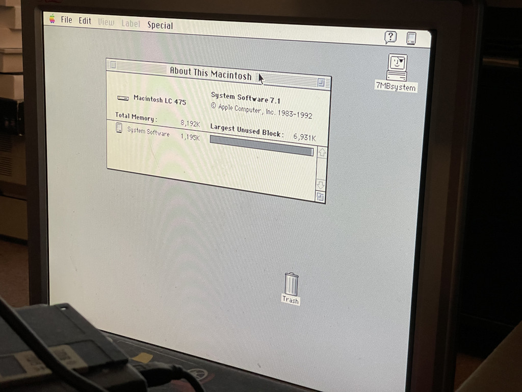
And of course, here is the result of Joakim’s incredible work, showing my LC 475 booting from a 7 MB ROM disk courtesy of Rob Braun’s driver:
This is simultaneously good news and bad news. The good news is we now know how to use ROM SIMMs in the Quadras. The bad news is we’re all doing it wrong! As of this writing, nobody is currently making a programmable ROM SIMM that is working the intended way with the Quadras. I know that people have tested modern programmable SIMMs in the Quadra 700/900/950 and 610/650/800 and they seem to work, but I’m concerned that there is some luck involved. The onboard ROMs are still enabled, but the chips on the SIMM seem to be overpowering them. On the 475, Joakim observed a problem with this until we actually disabled them. It’s probably also bad for all of the chips if they’re fighting against each other.
The Apple Interactive Television Box is an exception that works perfectly fine with existing programmable SIMMs out there. That’s because it doesn’t have any onboard ROMs for the SIMM to be fighting against. If it did have onboard ROMs, it would likely be running into the same problem that Joakim observed on the 475 since the STB is based on the LC 475.
So what does this all mean? It means the programmable ROM SIMM pinout needs to change in order to be 100% compatible with the Quadras. But how can we do it in a way that’s still compatible with the SE/30 and II-series Macs? Let’s summarize the pinout differences in a table:
| Pin Number | SE/30, II series function | Quadra function |
|---|---|---|
| 2 | A0 | VPP (12V) |
| 3 | A1 | /WE |
| 11 | /CS | Always +5V to disable onboard ROMs (SIMM chips have /CS tied to GND instead) |
| 12 | /OE | /OE |
| 13 | +5V (/WE in my programmer) | +5V |
This becomes an interesting challenge. How do you make a ROM SIMM that is compatible with both the old-style and new-style pinouts? Is it safe to tie /CS directly to +5V on a SIMM that is inserted in older machines? Is there a risk you’d damage something? Bonus points if you can make the SIMM theoretically compatible with in-system programming in Quadras too.
To answer my question above, you can’t tie pin 11 directly to +5V if you’re planning on inserting the SIMM in an old Mac. The SE/30, IIcx, and IIfx tie pins 11 and 12 together on the logic board, so forcing pin 11 to +5V will also disable the /OE signal and the ROM won’t work at all. The IIci and IIsi, in comparison, directly connect pin 11 to GND, so tying it to +5V on the SIMM will create a short circuit between +5V and GND. Not good!
So the pinout definitely has to change. But do we really want to have two separate SIMM models with different pinouts? That would be confusing for people. And if we want to have /WE mapped correctly in the Quadras to pin 3 for potential in-system programming, it would no longer be compatible with my programmer. I don’t think it’s reasonable at this point to change the programmer pinout now that so many people have them.
Maybe there’s a way to leverage the presence of 12V on pin 2 as an automatic switch to decide whether it’s an old or new system and automatically remap the pins? When the SIMM is inserted in old machines or the programmer, pin 2 will either be floating or an address line, so nowhere near 12V. So that would leave it configured the old way. When 12V is on pin 2, it would be configured the new way instead. I get nervous involving 12V in a circuit that could potentially interact with signals on the logic board though. If it’s done with a transistor and somehow the transistor fails shorted, is there the possibility of sending 12V somewhere it shouldn’t be? If I’m being completely realistic here, automatically switching it is also way above my head. I’m more of a firmware guy than a hardware guy.
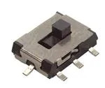
My current line of thinking is it might be easier to just add a physical switch on the SIMM, if there’s such thing as a small 3PDT switch:
- Pole 1: connect chip /CS to SIMM pin 11 (IIsi mode) or GND (Quadra mode)
- Pole 2: connect SIMM pin 11 to nothing (IIsi mode) or +5V (Quadra mode)
- Pole 3: connect chip /WE to SIMM pin 13 (IIsi mode) or SIMM pin 3 (Quadra mode)
- This last one is optional, but it would potentially allow in-system programming on Quadras assuming we figure out how to do it.
When used in a programmer or in the existing supported Macs, the switch would need to be set to IIsi mode. When used in a newer Mac like a Quadra, the switch would be set to Quadra mode. If a single switch like that doesn’t exist, maybe it could just be a block of 5 SPST DIP switches instead. The DIP switches would be confusing because you would have to turn some of them on and others off though, so it would be preferable to have a single combined switch.
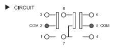
I think this switch on Mouser might do the trick nicely, as long as there is physical space for it. In Mouser’s search results it comes up as a 3PDT switch, but it really seems to be a DPDT switch and SPST switch combined as one, for a total of 8 pins — which is actually exactly what this would need. Pole 2 in my description above only needs to be a single-throw pole, so it would work perfectly with switch pins 7 and 8 in the circuit diagram below.
The main worry I have here is if someone accidentally leaves the SIMM in Quadra mode when they plug it into the programmer. I don’t love the thought of putting a ROM SIMM into the programmer if pin 11 is tied to +5V. The programmer is going to try to control pin 11 thinking it’s the chip select signal, but it would actually be tied directly to +5V on the SIMM. I worry this could damage the GPIO pin. It really means the programmer should have a series resistor on that line. It would also interfere with the electrical test functionality that the programmer firmware provides for detecting shorts. So it would be pretty important to make sure you put it in IIsi mode before inserting it in the programmer. Alternatively, the programmer could be tweaked to work with SIMMs in both IIsi and Quadra mode by putting a pulldown resistor on pin 11 instead of driving it low, and tying pins 3 and 13 together so /WE would be present on both. It would still interfere with the electrical test functionality, but I don’t think there’s any way around that.
I still think that overall, I lean toward the switch solution though. It’s probably better to avoid making hardware changes to the programmer at this point since so many people already have them.
Does anybody have any brilliant suggestions for Quadra compatibility that would be simpler than a switch? I don’t actually make or sell SIMMs anymore so it doesn’t really matter for me, but I’m wanting to raise awareness of this issue for people who might plan on tinkering with programmable ROMs in a Quadra.


Nothing comes to mind past using a switch, especially when in the hands of end users. Even then instructions can be confused and lead to errors. The solution is simple, new rom simms with edge connectors on the top AND bottom!
Haha, that’s an interesting idea Drake! Basically turning the SIMM itself into a switch. There are 3 GND pins on the SIMM pinout. If it’s safe to sacrifice one of them on the Quadra side to dedicate to the /CS pins of the chips (and also connect it to pin 11 of the IIsi side’s edge connector), I think that would actually work! It would look crazy, but it would work!
Would also be lots of fun to route!
I think your automatic +12V detection is the best solution, since it eliminates any possibility that the user could put the switch in the wrong position and cause trouble. Something like a TMUX4053 3-channel analog switch would be perfect for this, and could control the three poles in the way you proposed for the analog switch.
You could use a two-resistor voltage divider on SIMM pin 2 (VPP or A0 or N.C.) to lower the 12V down to a range that’s usable as a control signal for the TMUX4053. Its Vil is 0.8V and Vih is 1.35V. If you build a voltage divider that reduces the voltage to 1/7 the original value then you’d get 1.7V in a Quadra and at most 0.7V in a Mac II, so it should work as a control signal for the TMUX.
Sorry, I meant the TMUX could control the three poles in the way you proposed for the mechanical 3PDT switch.
If you want a slightly more robust solution for the control signal that doesn’t get so close to the Vil and Vih margins, you could use a typical NPN transistor switch circuit with SIMM pin 2 connected through a resistor of about 20K ohm to the transistor’s base and a 1K pull-up to 5V at the collector. That should give you a nice clean 0 or 1 input to the TMUX. Basically you would be building using this circuit: https://www.petervis.com/GCSE_Design_and_Technology_Electronic_Products/transistor_base_resistor_calculator/transistor_base_resistor_calculator.html
Do you know if all Quadras which require this different pinout have +12V present? Or could there be some Quadras that require the new pinout but don’t have +12V and don’t support in-system programming? If that’s possible, then it would need a different method of mode detection than pin 2 VPP. Maybe a one-shot circuit on /CS that triggers if the signal ever goes high, which would indicate a Mac II. If /CS never goes high, then it’s a Quadra.
Thanks BMOW! Super awesome ideas. I wish I had your amazing hardware knowledge and skills!
Your automatic switch idea with the analog mux seems great. And I’m assuming as long as you use high enough resistance values in the voltage divider it wouldn’t really hurt the A0 line in the address bus at all if pin 2 is A0. Or just use the transistor solution you suggested. Both of those sound nice to me because it limits the 12V to only a minor part of the circuit.
So far, every Quadra I’ve checked has +12V on pin 2 and something going from pin 3 to one of the Apple ASICs for (presumably) in-system programming. Here are the ones I can verify 100% due to having them on-hand:
– 475
– 610
– 630
– 660av
– 840av
I’ve also been told that the 575, 700, 800, and 900 match this scheme. I think between those lists, we pretty much have the entire Quadra line covered except for a few in the same families like the 650 that are likely the same.
There are also a few 030 Macs like the Color Classic and the IIvx. I’m not sure on the IIvx but I assume it’s going to be the same. The Color Classic is kind of weird, but I’m not worried about it because it has some of the upper address lines of the ROM SIMM socket wired up weirdly so it would need something weird anyway (I think).
On the one-shot circuit — my brain’s fried from hacking up one of my old 8 MB SIMMs with the switch today (the switch works!), but it kind of scares me that before we’ve seen the signal go high, we wouldn’t necessarily know the correct configuration. I really don’t think it’s necessary though…12V seems to be pretty ubiquitous on these Quadras.
Here’s my crazy bodge wiring with the manual switch. This took me hours to do! I tested this in my IIci and programmer with the switch to the left, and in my 475 with the switch to the right, and it works correctly in everything.
Excellent, nice wiring job! So you’ve got proof of concept. Yes with a reasonably large resistance in the voltage divider then it should have negligible effect on A0. Using standard resistor values, a voltage divider with 51K and 8.2K resistors should work.
Thanks! That makes perfect sense to use larger resistor values.
After having played with my prototype with the switch for an hour or so, I have changed my mind. You’re absolutely right, the slide switch is going to be a problem. It works just fine electrically, but it doesn’t take into account the human factor. I’ve been thinking a lot about the switch lately, and I still almost always forget to flip it when I’m swapping it between the programmer and the LC 475. Everyone is going to constantly forget to flip the switch.
For extra style points, you could also connect the control signal to the highest address line on the flash chips, and program two different ROM images into the SIMM, one in the lower half and one in the upper half. Them the SIMM would automatically use the correct ROM image for whatever computer it was installed in – assuming all the Quadras can use the same ROM image, which I’m not sure about. If you do that, I’d recommend using the transistor solution instead of the voltage divider.
OK last post on this for a while, I promise. Here’s what I think you should do: forget my voltage divider or transistor ideas, and use a small voltage comparator IC like AS393AMTR-G1. It compares two voltages and gives you a binary output signal depending whether V2 > V1 or not. It’s $0.10 at DigiKey and will be more robust than the other approaches, since it’s purpose-made for this kind of application and will have a nice sharp transition at the crossover point. For the two voltages being compared you’ll want two voltage dividers: one that divides +5V by 2 to get a 2.5V reference, and another that divides SIMM pin 2 by 4. The comparator output will be asserted if SIMM pin 2 is above 10V since 10/4 = 2.5. Other values could work too.
This way you won’t need to worry about approaching the digital logic input thresholds, or about the actual transistor gain, or other parameters. The downside is that it’s a 2-chip solution (including the TMUX) with four resistors, so it’s not quite as simple as just a two resistor divider plus the TMUX.
Actually just use +5V directly as the V1 reference, and SIMM pin 2 divided by 2 as the V2 reference. Same result, fewer resistors needed.
Ooh nifty! I think a universal Quadra ROM isn’t something we currently have, unfortunately. It may need to be a tad more model-specific.
I like the comparator idea. I was about to ask if it would work properly if pin 2 is floating too, but after staring at a voltage divider schematic I am confident the bottom resistor will act as a pull-down if the input voltage is floating. I like it!
I’d be tempted to do the 12 volt detection idea, but throw an opto-isolator between the 12V and logic-level sections of that circuit.
That’s an interesting idea Will. It would definitely guarantee separation even if something bad happened with the resistor divider circuit…
[…] I wrote about the possibility of programmable Mac ROM SIMMs in Quadras a couple of months ago, I suspected that there had been a way for developers at Apple in the 68k […]
[…] Brown wrote about the possibility of programmable Mac ROM SIMMs in Quadras a couple of months ago. He suspected that there had been a way for developers at Apple in the 68k […]
Just wanted to mention that on the ROM DIMM for X100 PowerMac and later (through Beige G3), pin 116 is connected to the Motherboard ROM chips, so tying it high disables motherboard ROM on machines that have it.
Not relevant to the Beige G3 or the X100 machines, actually, as they’re always socketed, but it matters on the first PCI PowerMacs, 7200, 7500, 8500, 9500 and X600 variants.