I bet you thought I gave up on these lessons! In my last post about microcontrollers, I introduced the idea of an interrupt-safe circular buffer. I briefly mentioned that circular buffers are commonly used in software drivers for peripherals that send and/or receive a lot of data. One example in particular that I gave was a UART (universal asynchronous receiver/transmitter). I’d like to expand further on UARTs in this post.

How they work

First of all, what is a UART? Well, let’s break down the acronym:

  • Universal: The device can be configured for different modes/speeds.
  • Asynchronous: The communication does not use a separate clock wire for synchronization; it’s all handled only with a single data wire in each direction.
  • Receiver: It can receive data…
  • Transmitter: …and it can transmit data.

That’s great, but it still doesn’t really explain anything about what the UART does. It’s easier to describe a UART by talking about a computer serial port. If you’re geeky like me, I’m sure you’ve dealt with serial ports before. For example, if you’re a Raspberry Pi aficionado, you might have a USB-to-TTL serial adapter that you hook up to the Pi to access its Linux console. On your computer, you use a program like PuTTY or minicom to open the port for 115,200 baud, 8 data bits, no parity, and 1 stop bit. Then, you can turn on the Pi and see all of the messages it sends at boot. After the operating system is fully booted, you can also enter commands on the console.

If you have done this, you have actually worked with a UART. A UART is this whole interface I just described. You configure it for a baud rate as well as various framing parameters (7-bit data? 8-bit data? 1 stop bit? 2 stop bits? parity bits?). Then you send it bytes. It turns each byte into a sequence of 1s and 0s with a prepended start bit and an appended stop bit or two (there’s also an optional parity bit that can be added to the mix to try to detect errors). Finally, it sends this final sequence of bits onto a transmit pin at the configured bit rate. It also listens on a receive pin for data coming in with that kind of format and parses the serial bits back out into parallel bytes.

On the hardware side of things, let’s go through an example of sending out an uppercase ‘M’ with a UART configured in 8N1 mode. This means there are 8 bits per byte, no parity bit, and 1 stop bit. We start out by telling the UART to send the character ‘M’ which is represented as 0x4D according to an ASCII table. 0x4D in binary is “01001101”. A 1 represents a high state and a 0 represents a low state. The start bit is always a 0 and the stop bit is always a 1.

UART-Diagram

If you transmitted the character ‘M’ and looked at it on an oscilloscope, this is what you’d see. While the UART is inactive, it keeps the pin at a high state. Thus, the start bit is low so you can detect the start of a transmission. After the stop bit, if there is no more data to be sent, the pin stays high until the next start bit begins.

Hopefully this diagram makes sense. You’ll see that the bits are in reverse order because they are sent least-significant first. The horizontal unit on this diagram is time; the vertical lines are each about 8.7 microseconds apart, assuming the baud rate is set to 115200. I got that by calculating the reciprocal of the bit rate. If the bit rate is 115,200 bits per second, then there are (1/115200) seconds per bit.

The receiver looks for this pattern and interprets the bits between the start and stop bit. That’s really all there is to it! UARTs were very common on computers of the past generations. Earlier computers used a separate chip just for the UARTs, like the 8250 or the 16550A. In fact, many UARTs to this day remain software-compatible with the 16550A. Later on, computers began including a Super I/O chip with integrated 16550A-compatible UARTs.

How to use them

In microcontrollers, you typically find a UART (or multiple UARTs) available as memory-mapped peripherals. Sometimes they use the same interface as the 16550A, and sometimes not. For simplicity I’m going to talk about an AVR’s UART in this lesson instead of the 16550A. The 16550A is complicated because it has a couple of built-in 16-byte FIFO buffers for transmitting and receiving along with a fairly strange interrupt setup because of the FIFOs. The FIFOs are important for normal desktop computers because if your computer had to deal with an interrupt on every character, it would get bogged down handling the interrupts. The FIFO allows interrupts to occur less frequently. On a simple microcontroller like an AVR, handling an interrupt on every character is not a huge problem. Because of the lack of a FIFO, the AVR’s software interface will be easier to understand, which makes it appropriate for this introductory lesson.

I’m going to be using the AT90USB646 as an example. This is the same processor that I use on my Mac ROM SIMM programmer. It has a single USART. Notice the extra S? USART stands for Universal Synchronous/Asynchronous Receiver/Transmitter. It just adds the ability to work in a synchronous mode with an external clock pin. For our purposes, we won’t worry about this. We’ll be using it in asynchronous mode.

The AT90USB646 reference manual says that this chip has a single USART, described in chapter 18. It provides some sample code in both assembly and C for talking to the UART. It’s really not that hard to do.

Setting the baud rate

The baud rate is set with two registers: UBRR1L and UBRR1H. They are the low and high bytes of the full register UBRR1 (which you can also access directly as a 16-bit word, at least in AVR-GCC and AVR Libc). The equation, as per the datasheet, is:

UBRR1 = (oscillator_frequency / (16*baud_rate)) – 1;

So let’s use my SIMM programmer board as an example. It has a 16 MHz crystal, and let’s pretend we’re going for a baud rate of 9600. Thus, I should do:

UBRR1 = (16000000UL / (16*9600UL)) - 1;

Note that I used UL at the end of these constants to ensure they’re being treated as unsigned long integers. Otherwise, the intermediate calculations might get messed up due to only being promoted to 16-bit values. Your development environment will probably provide a define for the clock rate. Plus, it’s usually a good idea to create a #define for your baud rate instead of hardcoding a 9600UL randomly in the code. So it’s actually better to do this:

#define MY_BAUD_RATE 9600UL
UBRR1 = (F_CPU / (16*MY_BAUD_RATE)) - 1;

If you do the math (and integer truncation) yourself, you will discover that this will assign UBRR1 a final value of 103. Mathematically, it would be 103.166666666…, but it will get truncated down to an integer. This also means the baud rate won’t be exactly 9600 baud. If we solve the equation above for baud_rate and put our calculated/truncated UBRR1 value of 103 back in, you’ll see that we don’t get exactly 9600 baud:

baud_rate = oscillator_frequency / (16*(UBRR1 + 1));

baud_rate = 16000000 / (16*(103 + 1));

This gives us a baud rate of 9615. The AVR will actually be transmitting and receiving at 9615 baud. That’s an error of about 0.16%, which is definitely close enough to 9600 baud that it won’t be a problem. Usually you’re in good shape if you’re within a percent or two, and we are much closer than that. Keep in mind that oscillators aren’t perfect either, so UARTs are tolerant of baud rates that aren’t exactly correct.

Configuring the framing

We have to make sure that the USART knows what type of data to send and receive. Should there be 5 data bits? 8 data bits? 1 stop bit? 2 stop bits? Parity? No parity? All of this can be configured in some of the registers in the USART. The registers are called UCSR1A, UCSR1B, and UCSR1C. UCSR is short for “USART Control and Status Register”. These registers contain bits for controlling the setup of the USART as well as some bits that signal status of the USART.

The bits that are important for us to configure in order to get basic functionality are the following:

  • U2X1 bit (bit 1) of UCSR1A. This is a double-speed bit that essentially turns the constant “16” in the baud rate calculation formula above into an “8” — we should make sure it’s disabled since we assumed in the baud rate calculation we did earlier that it was in fact 16.
  • RXEN1 bit (bit 4) of UCSR1B. This bit enables the receiver so we can receive incoming bytes.
  • TXEN1 bit (bit 3) of UCSR1B. This bit enables the transmitter so we can send outgoing bytes.
  • UCSZ12 bit (bit 2) of UCSR1B and UCSZ11, UCSZ10 bits (bits 2 and 1) of UCSR1C. These three bits combine together to determine the number of data bits (5 to 9).
    • 0 –> 5 bits
    • 1 –> 6 bits
    • 2 –> 7 bits
    • 3 –> 8 bits (what we want)
    • 4, 5, 6 reserved
    • 7 –> 9 bits
  • UMSEL11, UMSEL10 bits (bits 7 and 6) of UCSR1C. These bits determine the mode (synchronous/asynchronous) of the USART.
    • 0 –> asynchronous (what we want)
    • 1 –> synchronous
    • 2 –> reserved
    • 3 –> master SPI (this USART is capable of being an SPI master; I have discussed SPI in the past)
  • UPM11, UPM10 bits (bits 5 and 4) of UCSR1C. These bits determine the parity mode (none, even, or odd).
  • USBS1 bit (bit 3) of UCSR1C. This bit determines if there is 1 stop bit or 2 stop bits.

So basically, we need to set up these three registers:

UCSR1A = 0; // Not double speed mode, disable address filtering
UCSR1B = 0x18; // Enable RX and TX, high bit of UCSZ1 = 0
UCSR1C = 0x06; // asynchronous, no parity, 1 stop bit, 8 data bits

AVR Libc has some nice macros for the various bit names, so you can also do this with the symbolic names:

UCSR1A = 0;
UCSR1B = (1 << RXEN1) | (1 << TXEN1);
UCSR1C = (3 << UCSZ10);

Transmitting data

After you have configured the USART correctly, it’s very easy to send and receive. To send data, you simply write the character you wish to send into the UDR1 register. Here’s an example of transmitting the character ‘A’:

UDR1 = 'A';

You can only transmit if the hardware has finished transmitting the last character. This is because the USART does not have a transmit FIFO. Because of this, you need to check a status bit to ensure the transmitter is not already busy:

if (UCSR1A & (1 << UDRE1)) {
    UDR1 = 'A';
}

This will only transmit a character if the transmit buffer is empty. Otherwise, it won’t transmit. If you need to make sure the character is transmitted, you can wait until the bit goes high:

while (!(UCSR1A & (1 << UDRE1))) {
}
UDR1 = 'A';

So you do an empty loop until the bit goes high, after which it’s safe to write to the transmit buffer.

Receiving data

Receiving is very, very similar. First, you need to know if a character is ready to be received. The hardware will tell you if a character is waiting to be read by making a bit high in the UCSR1A register. If the bit is high, you can read the character by reading the UDR1 register:

if (UCSR1A & (1 << RXC1)) {
    received_char = UDR1;
    // do something with the received character
}

The receiver actually has a FIFO (first-in, first-out) buffer to hold a couple of received characters in case your program is unable to read the first character received before another one arrives. This is a nice little safety mechanism to have, but you still need to read received characters quickly before the small FIFO fills up. Fancier UARTs have a bigger receive buffer to enable high data rates with less processor utilization.

Example code

Here’s a sample program that will echo back any character that is received. If you type the letter ‘Z’, it will transmit the letter ‘Z’ right back to you.

#include <avr/io.h>

#define MY_BAUD_RATE 9600UL

int main(void) {
    UBRR1 = (F_CPU / (16*MY_BAUD_RATE)) - 1;
    UCSR1A = 0;
    UCSR1B = (1 << RXEN1) | (1 << TXEN1);
    UCSR1C = (3 << UCSZ10);
    
    while (1) {
        while (!(UCSR1A & (1 << RXC1)));
        uint8_t ch = UDR1;
        while (!(UCSR1A & (1 << UDRE1)));
        UDR1 = ch;
    }
}

It’s really not that complicated. It waits until a character is received, and then receives it. Then it waits until the transmitter is empty, and transmits the received character. Note that I put semicolons at the end of the while() loops waiting for the bits. This was done intentionally to save space over giving them an empty loop body, but it can be a little confusing to read, so I wanted to explicitly point that out.

Anyway, this whole thing is easy, right?

Interrupts

There’s a catch. If your program has to do anything other than sit in a loop waiting for a character to arrive over the UART, this whole idea starts to fall apart. If you don’t check for received data often enough, you will run the risk of losing received characters. This could happen if the receive FIFO is filled before you get around to checking the UART again. How do we solve this dilemma?

You may have been wondering why I mentioned circular buffers at the beginning of this post. What do circular buffers have to do with anything I have mentioned so far? Good news: you’ve finally reached the point in this post where everything will start to come together and make sense.

The solution to this problem is to handle the UART with an interrupt. Whenever a character is received, the UART will fire an interrupt. This will cause your main program to temporarily jump to an interrupt handler which reads the received character from the UDR1 register and stores it in a circular buffer. Somewhere in the main loop, you can occasionally check the circular buffer to see if it contains any characters and process them. As long as the buffer is big enough so that you will check it before it fills up, it will solve the problem.

On the other end, you can also create a separate circular buffer for transmitting over the UART. This will allow you to put the data into the circular buffer and then move on to other places in your program while the data is sent in the background by your interrupt handler. Basically, it prevents you from having to sit in a loop and wait for all of your characters to be transmitted before you can move onto other tasks.

This a perfect application for a circular buffer. It’s easy to make a circular buffer interrupt-safe as long as you insert from the main loop and remove from the interrupt handler (or vice versa), and inserting and removing from it are both O(1) operations. This is exactly what we need for both the transmitting and receiving end of things.

The AVR’s USART is really handy because it has what’s known as the UDRE interrupt, which stands for USART data register empty. This interrupt fires anytime the transmit data register is ready for you to write another character. It’s based on the same status bit we checked in the non-interrupt-driven code above. So if the USART is idle, this interrupt will fire. Because of this interrupt, there are no special cases when you first start transmitting characters. When you put a character in the TX buffer, you have to ensure that the UDRE interrupt is enabled. In your UDRE interrupt handler, if the TX buffer is empty, you disable the UDRE interrupt. This logic is very simple compared to other UARTs, which often require special cases when you transmit your first character in order to get the interrupts rolling.

Example code

Here’s some sample code I wrote for interrupt-driven UART functionality. It consists of a header file and source file for the UART driver. You will notice the ring buffer functions which I renamed and borrowed from my post about ring buffers. Many AVR microcontrollers have multiple USARTs. This particular one works with USART1 on the AT90USB646.

uart.h:

#ifndef UART_H_
#define UART_H_

#include <stdbool.h>
#include <stdint.h>

void uart_init(uint32_t baud);
void uart_write_char(char data);
char uart_read_char(void);
bool uart_rx_buffer_empty(void);
bool uart_tx_buffer_empty(void);
bool uart_rx_buffer_full(void);
bool uart_tx_buffer_full(void);

#endif /* UART_H_ */

uart.c:

#include "uart.h"
#include <avr/io.h>
#include <avr/interrupt.h>

#define RING_SIZE   128
typedef uint8_t ring_pos_t;

static volatile ring_pos_t tx_ring_head;
static volatile ring_pos_t tx_ring_tail;
static volatile char tx_ring_data[RING_SIZE];

static volatile ring_pos_t rx_ring_head;
static volatile ring_pos_t rx_ring_tail;
static volatile char rx_ring_data[RING_SIZE];

static int tx_ring_add(char c);
static int tx_ring_remove(void);
static int rx_ring_add(char c);
static int rx_ring_remove(void);

void uart_init(uint32_t baud) {
    // TODO: if you are OK with hardcoding the bit rate,
    // consider using avr-libc's <util/setbaud.h>
    // functionality instead.

    // Set baud rate
    UBRR1 = (F_CPU / (16*baud)) - 1;
    // Enable RX and TX, turn on RX interrupt,
    // turn off data register empty interrupt until needed
    UCSR1B = (1 << RXEN1) | (1 << TXEN1) | (1 << RXCIE1);
    // 8 data bits, 1 stop bit
    UCSR1C = (3 << UCSZ10);

    // Clear out head and tail just in case
    tx_ring_head = 0;
    rx_ring_head = 0;
    tx_ring_tail = 0;
    rx_ring_tail = 0;
}

void uart_write_char(char data) {
    // Wait until there's room in the ring buffer
    while (uart_tx_buffer_full());

    // Add the data to the ring buffer now that there's room
    tx_ring_add(data);

    // Ensure the data register empty interrupt is turned on
    // (it gets turned off automatically when the UART is idle)
    UCSR1B |= (1 << UDRIE1);
}

char uart_read_char(void) {
    // Wait until a character is available to read
    while (uart_rx_buffer_empty());

    // Then return the character
    return (char)rx_ring_remove();
}

bool uart_rx_buffer_empty(void) {
    // If the head and tail are equal, the buffer is empty.
    return (rx_ring_head == rx_ring_tail);
}

bool uart_tx_buffer_empty(void) {
    // If the head and tail are equal, the buffer is empty.
    return (tx_ring_head == tx_ring_tail);
}

bool uart_rx_buffer_full(void) {
    // If the head is one slot behind the tail, the buffer is full.
    return ((rx_ring_head + 1) % RING_SIZE) == rx_ring_tail;
}

bool uart_tx_buffer_full(void) {
    // If the head is one slot behind the tail, the buffer is full.
    return ((tx_ring_head + 1) % RING_SIZE) == tx_ring_tail;
}

static int tx_ring_add(char c) {
    ring_pos_t next_head = (tx_ring_head + 1) % RING_SIZE;
    if (next_head != tx_ring_tail) {
        /* there is room */
        tx_ring_data[tx_ring_head] = c;
        tx_ring_head = next_head;
        return 0;
    } else {
        /* no room left in the buffer */
        return -1;
    }
}

static int tx_ring_remove(void) {
    if (tx_ring_head != tx_ring_tail) {
        int c = tx_ring_data[tx_ring_tail];
        tx_ring_tail = (tx_ring_tail + 1) % RING_SIZE;
        return c;
    } else {
        return -1;
    }
}

static int rx_ring_add(char c) {
    ring_pos_t next_head = (rx_ring_head + 1) % RING_SIZE;
    if (next_head != rx_ring_tail) {
        /* there is room */
        rx_ring_data[rx_ring_head] = c;
        rx_ring_head = next_head;
        return 0;
    } else {
        /* no room left in the buffer */
        return -1;
    }
}

static int rx_ring_remove(void) {
    if (rx_ring_head != rx_ring_tail) {
        int c = rx_ring_data[rx_ring_tail];
        rx_ring_tail = (rx_ring_tail + 1) % RING_SIZE;
        return c;
    } else {
        return -1;
    }
}

ISR(USART1_RX_vect) {
    char data = UDR1;
    rx_ring_add(data);
}

ISR(USART1_UDRE_vect) {
    if (!uart_tx_buffer_empty()) {
        // Send the next character if we have one to send
        UDR1 = (char)tx_ring_remove();
    } else {
        // Turn off the data register empty interrupt if
        // we have nothing left to send
        UCSR1B &= ~(1 << UDRIE1);
    }
}

Finally, here’s a test program that tests out the USART:

#include <avr/interrupt.h>
#include "uart.h"

int main(void) {
    cli(); // disable interrupts
    uart_init(9600);
    sei(); // enable interrupts
    while (1) {
        uart_write_char(uart_read_char());
    }
}

This particular sample program doesn’t really take advantage of the fact that the code is interrupt-driven, but at least it tests the code out. The interrupt-driven aspect of the code shines when you need to send a 50-byte string and don’t want to wait around until it finishes sending. With this code, if you quickly write 50 bytes, the program will continue doing other things while the 50 bytes are sent in the background as interrupts come in. For receiving, you can let your program do many things without worrying about losing a received character. Every time through your main loop, you should process all characters that are waiting in the receive buffer to ensure that it doesn’t fill up.

Other functions

You could easily add other functions for transmitting a string, receiving a full line, etc. It would probably be nice for the transmit and receive functions to have optional parameters to tell them not to block if the buffers aren’t ready. These are all excellent exercises I leave to you, the reader, to implement.

Conclusion

I hope this explains the UART/USART in enough detail to get you started. This is a very important peripheral that is commonly used for interfacing with displays, sensors, and other microcontrollers. If you’re going to use a UART/USART, I would highly recommend that you do it with interrupts as I described above. This is definitely the type of thing you should stick into your toolbox of peripheral drivers and reuse on all of your projects.

I’ve seen plenty of articles about this topic already, but I’d like to talk about it on my blog as well. It’s a pretty important topic in my opinion.

Let’s say you have a microcontroller peripheral that sends and/or receives a bunch of data. A good example of this type of microcontroller peripheral is a UART (universal asynchronous receiver/transmitter). That’s essentially a fancy name for a serial port–you know, the old 9-pin connectors you’d find on PCs. They were commonly used for connecting mice and modems back before PS/2, USB, and broadband took over. A UART basically does two things: receives data and transmits data. When you want to transmit data, you write a byte to a register in the UART peripheral. The UART converts the 8 bits into a serial data stream and spits it out over a single wire at the baud rate you have configured. Likewise, when it detects an incoming serial data stream on a wire, it converts the stream into a byte and gives you a chance to read it.

I’m actually not going to go into detail about UARTs yet because I feel it’s really important to understand a different concept that we will need to know when we learn about how to use UARTs. That concept is an interrupt-safe circular buffer. This lesson is dedicated to understanding this very important data structure. The next post I write will then go into more detail about UARTs, and that post will use a concept that you will learn about in this post. OK, let’s get started with circular buffers.

A common problem when you are receiving or transmitting a lot of data is that you need to buffer it up. For example, let’s say you want to transmit 50 bytes of data. You have to write the bytes one-by-one into the peripheral’s data register to send it out. Every time you write a byte, you have to wait until it has transmitted before writing the next byte. (Note: Some microcontroller peripherals have a hardware buffer so you can write up to 16 [for example] bytes before you have to wait, but that hardware buffer can still fill up, so this concept I’m describing still applies)

A typical busy loop sending the data would look like this:

char data[50]; // filled with data you're transmitting

for (int x = 0; x < 50; x++) {
    while (peripheral_is_busy());
    peripheral_send_byte(data[x]);
}

This loop is simple. For each of the 50 bytes, it first waits until the peripheral isn’t busy, then tells the peripheral to send it. You can imagine what implementations of the peripheral_is_busy() and peripheral_send_byte() functions might look like.

While you’re transmitting these 50 bytes, the rest of your program can’t run because you’re busy in this loop making sure all of the bytes are sent correctly. What a waste, especially if the data transmission rate is much slower than your microcontroller! (Typically, that will be the case.) There are so many more important tasks your microcontroller could be doing in the meantime than sitting in a loop waiting for a slow transmission to complete. The solution is to buffer the data and allow it to be sent in the background while the rest of your program does other things.

So how do you buffer the data? You create a buffer that will store data waiting to be transmitted. If the peripheral is busy, rather than waiting around for it to finish, you put your data into the buffer. When the peripheral finishes transmitting a byte, it fires an interrupt. Your interrupt handler takes the next byte from the buffer and sends it to the peripheral, then immediately returns back to your program. Your program can then continue to do other things while the peripheral is transmitting. You will periodically be interrupted to send another byte, but it will be a very short period of time — all the interrupt handler has to do is grab the next byte waiting to be transmitted and tell the peripheral to send it off. Then your program can get back to doing more important stuff. This is called interrupt-driven I/O, and it’s awesome. The original code I showed above is called polled I/O.

You can probably imagine how useful this idea is. It will make your program much more efficient. If you’re a computer science person, you’re probably thinking,  “Doug, the abstract data type you should use for your buffer is a queue!” You would be absolutely correct. A queue is a first-in, first-out (FIFO) data structure. Everything will come out of the queue in the same order it went in. There’s no cutting in line! (Well, unless you have a bug in your code, which I’m not afraid to admit has happened to me enough times that I finally bothered to write up this article so I’ll have a reference for myself.) Anyway, that’s exactly how we want it to be. If I queue up “BRITNEYSPEARS” I don’t want it to be transmitted as “PRESBYTERIANS”. (Yes, amazingly enough, that is an anagram.)

A really easy to way to implement a queue is by creating a ring buffer, also called a circular buffer or a circular queue. It’s a regular old array, but when you reach the end of the array, you wrap back around to the beginning. You keep two indexes: head and tail. The head is updated when an item is inserted into the queue, and it is the index of the next free location in the ring buffer. The tail is updated when an item is removed from the queue, and it is the index of the next item available for reading from the buffer. When the head and tail are the same, the buffer is empty. As you add things to the buffer, the head index increases. If the head wraps all the way back around to the point where it’s right behind the tail, the buffer is considered full and there is no room to add any more items until something is removed. As items are removed, the tail index increases until it reaches the head and it’s empty again. The head and tail endlessly follow this circular pattern–the tail is always trying to catch up with the head–and it will catch up, unless you’re constantly transmitting new data so quickly that the tail is always busy chasing the head.

Anyway, we’ve determined that you need three things:

  1. An array
  2. A head
  3. A tail

These will all be accessed by both the main loop and the interrupt handler, so they should all be declared as volatile. Also, updates to the head and updates to the tail each need to be an atomic operation, so they should be the native size of your architecture. For example, if you’re on an 8-bit processor like an AVR, it should be a uint8_t (which also means the maximum possible size of the queue is 256 items). On a 16-bit processor it can be a uint16_t, and so on. Let’s assume we’re on an 8-bit processor here, so ring_pos_t in the code below is defined to be a uint8_t.

#define RING_SIZE   64
typedef uint8_t ring_pos_t;
volatile ring_pos_t ring_head;
volatile ring_pos_t ring_tail;
volatile char ring_data[RING_SIZE];

One final thing before I give you code: it’s a really good idea to use a power of two for your ring size (16, 32, 64, 128, etc.). The reason for this is because the wrapping operation (where index 63 wraps back around to index 0, for example) is much quicker if it’s a power of two. I’ll explain why. Normally a programmer would use the modulo (%) operator to do the wrapping. For example:

ring_tail = (ring_tail + 1) % 64;

If your tail began at 60 and you repeated this line above multiple times, the tail would do the following:

61 -> 62 -> 63 -> 0 -> 1 -> …

That works perfectly, but the problem with this approach is that modulo is pretty slow because it’s a divide operation. Division is a pretty slow operation on computers. It turns out when you have a power of two, you can do the equivalent of a modulo by doing a bitwise AND, which is a much quicker operation. It works because if you take a power of two and subtract one, you get a number which can be represented in binary as a string of all 1 bits. In the case of a queue of size 64, bitwise ANDing the head or tail with 63 will always keep the index between 0 and 63. So you can do the wrap-around like so:

ring_tail = (ring_tail + 1) & 63;

A good compiler will automatically convert the modulo to the faster AND operation if it’s a power of two, so you can just use my first example with the “% 64” since it makes the intent of the code clearer. I’ve been told I have “a lot of faith in compilers” but it’s true–if you compile with optimizations enabled, GCC will correctly optimize my first example into the assembly equivalent of my second example. Looking at the assembly code that your compiler generates is a very valuable tool for you to have available.

OK. Now that I’ve explained everything, here are my add() and remove() functions for the queue:

int add(char c) {
    ring_pos_t next_head = (ring_head + 1) % RING_SIZE;
    if (next_head != ring_tail) {
        /* there is room */
        ring_data[ring_head] = c;
        ring_head = next_head;
        return 0;
    } else {
        /* no room left in the buffer */
        return -1;
    }
}

int remove(void) {
    if (ring_head != ring_tail) {
        int c = ring_data[ring_tail];
        ring_tail = (ring_tail + 1) % RING_SIZE;
        return c;
    } else {
        return -1;
    }
}

The add function calculates the next position for the head, ensures that there’s room in the buffer, writes the character to the end of the queue, and finally updates the head. The remove function ensures the buffer isn’t empty, grabs the first character waiting to be read out of the queue, and finally updates the tail. The code is pretty straightforward, but there are a couple of details you should be aware of:

  • I only modify the head index in the add function, and I only modify the tail index in the remove function.
  • I only modify the index after reading/writing the data in the buffer.

By doing both of the above, I have successfully ensured that this is an interrupt-safe, lock-free ring buffer (if there is a single consumer and a single producer). What I mean is you can add to the queue from an interrupt handler and remove from the queue in your main loop (or vice-versa), and you don’t have to worry about interrupt safety in your main loop. This is a really cool thing! It means that you don’t have to temporarily disable interrupts in order to update the buffer from your main loop. It’s all because of the two bullets above. If the interrupt only modifies the head, and the main loop only modifies the tail, there’s no conflict between the two of them that would require disabling interrupts. As for my second bullet point, updating the head or tail index only after the read or write is only necessary in whatever side of the queue is working in the main loop — it doesn’t matter in the interrupt handler. But if I follow that convention in both the add() and remove() functions, they can be swapped around as needed — in one program add() could be used in an interrupt handler and remove() could be used in the main loop, but in a different program, remove() would be in the interrupt handler and add() would be in the main loop.

OK, so back to the original example of transmitting 50 bytes. In this case, the main loop will use the add() function. You will add 50 bytes to the queue by calling add() 50 times. In the meantime, the microcontroller peripheral will interrupt every time it successfully sends a byte. The interrupt handler will call remove(), tell the peripheral to transmit the character it just removed, and give control back to the main loop. Later on, the transmission of that character will complete, the interrupt will occur again, it will send the next character, and so on until all 50 bytes have been sent, at which point the queue will be empty. It works like a charm!

The only problem remaining is that the first time you need to send a character, the transmitter isn’t running yet. So you have to “prime the pump” by telling the transmitter to start. Sometimes a peripheral will have a way to induce the first interrupt to get the ball rolling. Otherwise, you may have to add some extra logic that forces the first transmission to occur from the main loop. Since this technically breaks the “single consumer and single producer” rule, this one exception to the rule may still require some careful interrupt safety. I’ll talk more about that in a later post. The main purpose of this post is just to get you familiar with ring buffers and their inherent interrupt safety (aside from that one “gotcha”). They are very, very useful and very, very common. I’ve used them in drivers for UARTs and CANbus, and as I understand it, they are very common in audio applications as well.

I hope this made some sense. If it didn’t, I hope my next posting about UARTs will help clear things up.

Note: The information I have given may not be completely correct if you’re dealing with a system that has more than one processor or core, or other weird stuff like that. In that case you may need something extra such as a memory barrier between writing the queue data and updating the index. That’s beyond the scope of this article, which is targeted toward microcontrollers. This technique should work fine on microcontrollers with a single processor core.

Hi again everybody! I’ve decided to combine two blog posts into one: a product review and a new article in my microcontroller programming series. It’s a new concept that I’d like to explore for some of my microcontroller programming articles–concrete examples using actual products. Let me know if you’d like to continue to see posts like this in the future!

Introduction

Thanks to Newark/Farnell, I’ve had the opportunity to review several microcontroller development boards over the past year — see the product reviews category on my blog for more of these. Today, I will be reviewing the LPCXpresso OM11049 board. It’s a very simple development board with a built-in USB programming interface. You can plug it into your computer and use Code Red’s free LPCxpresso IDE to write code, compile it, and flash the resulting binary to the microcontroller. The microcontroller portion of the board is bare–it has nothing connected to the pins other than an LED connected to a single GPIO pin. The rest of the pins are brought out to headers. The idea is that you can create whatever circuit you’d like to use on a breadboard, plug the OM11049 board into your breadboard, and go from there. You can also buy a pre-made baseboard with peripherals already attached (1, 2, 3). For the purposes of this review/microcontroller series post, I’m going to stick with only using the OM11049 board by itself, though.

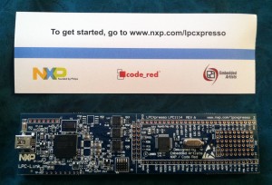
It comes in a plain-Jane envelope (forgive me, Grandma, for that terrible and inaccurate choice of cliché):

Here’s the board! It’s really long, and there’s a good reason for that. I’ll explain why in just a minute…

For those of you following the microcontroller series, you may be wondering where I’m going with this — it seems like a product review so far. What I’m going to do in the process of reviewing this board is walk through setting up a timer and GPIO as a real-world concrete example with code you can try out for yourself. In addition, I’m going to do it with interrupts, so we can see how to use a timer interrupt to keep track of time. This should apply knowledge you have picked up from my GPIO, timer, and interrupt articles. Ready? Let’s go!

The reason the OM11049 board is so long is because it’s actually two boards in one. The first half (on the left in the picture) is an LPC-LINK debugger, which appears to be implemented on an NXP LPC3154 chip. This half of the board is extremely useful because it allows us to program the contents of the microcontroller on the second half of the board without owning an expensive debugger board.

The other, more interesting half of the board is the target side of the board. This half of the board contains the microcontroller we will be programming. It has an NXP LPC1114/302 ARM Cortex-M0 microcontroller. According to the microcontroller’s datasheet, it can run at up to 50 MHz and it has 32 KB of flash memory, 8 KB of SRAM, one UART, one I2C peripheral, one SPI peripheral, 8 ADC channels, and 28 GPIO pins. For those of you who have been following my microcontroller series, you may recognize SPI and GPIO. For now, you can ignore the UART, I2C, and ADC capabilities — I will talk about them in future articles. Anyway, as I just said, this is a Cortex-M0. It’s very similar to the Cortex-M3 that I have mentioned in previous posts. I really like these types of microcontrollers because they’re 32-bit, easy to use, and common enough to find forum postings by plenty of other people using them when you need help.

In the schematic (see page 34) for the OM11049 board, we can see that there is a red LED connected to pin 23 (PIO0_7/CTS) of the microcontroller. We will need to remember this when we start writing some code.

Just a quick sidenote: you may notice that the LED is not the only thing connected to the pin–there is also a 2K resistor in series with the LED. The reason the resistor is there is because LEDs are only designed to have a certain amount of current running through them. If you allow too much current to flow through, you will blow the LED. The purpose of the resistor is to limit the current that can flow through the LED. (For those of you who took the electricity portion of a physics class, you may remember that V=IR, or rearranged, I=V/R. The higher the resistance [R], the lower the current [I].)

So let’s get started and set up the programming environment! By the way, if you don’t have a USB A-to-mini-B cable, you will need one in order to use the board — it does not come with one. However, pretty much everyone has such a cable these days, so I can’t really fault the makers of this board too much for not including one.

Setting up the programming environment

Install the LPCxpresso IDE, open it up, and follow the supplied directions to register it. Got that done? Good! Now let’s move on.

First of all, we need to import the CMSIS library for the LPC1114. In the LPCexpresso window in the bottom left, there should be a section called Start here with choices such as New project and Import project(s). Click Import project(s). Under Project archive (zip) click Browse. I’m not sure exactly where it will default to, but you want to go into the “lpcxpresso/Examples/NXP/LPC1000/LPC11xx” directory and choose “CMSISv2p00_LPC11xx.zip”. This will install the CMSIS libraries version 2.0. Click Next, make sure CMSISv2p00_LPC1xx is checked, and click Finish.

What is CMSIS?

CMSIS stands for “Cortex Microcontroller Software Interface Standard”.  It basically provides a set of functions and macros that are common between microcontrollers. Imagine you originally use a Cortex-M0 microcontroller from manufacturer #1, and then you decide to change to a Cortex-M0 made by manufacturer #2. A lot of the features between the two processors will be the same because they share the same microcontroller core. You shouldn’t have to rewrite a bunch of your code that works with the microcontroller core just because the two manufacturers organized their libraries differently. The idea behind CMSIS is to avoid the situation I just described by standardizing on the common functionality so it isn’t implemented differently in the libraries supplied by two different manufacturers. If you use a common peripheral like the SysTick timer (which we will do in this article–more on this later), you can expect it to work exactly the same between all Cortex-M0 processors.

It’s more than just that, though. The CMSIS libraries also include startup code that sets up the processor’s clock rate correctly and other similar things like that. They also tend to standardize how peripherals are accessed–the libraries tend to define a struct (e.g. struct LPC_TIMER) that contains all of the register definitions belonging to a peripheral. It further modularizes each peripheral and makes code easier to read. The bottom line is that CMSIS is a very good idea.

It’s not completely perfect, though. If you do SPI (for example) on a chip by manufacturer #1, chances are the SPI peripheral on the chip by manufacturer #2 has a completely different register layout. There’s nothing you can do about this — the peripherals are just plain different and CMSIS does not do any abstraction at this level. So you still end up having to write different code for that kind of stuff. Anyway, that’s enough about CMSIS. Back to the point of this article.

Continuing on…

Now, you’re ready to create a project for the LPC1114. Click on New project in the same bottom-left pane we used earlier. Click the arrow next to NXP LPC1100 projects and choose C Project. Click Next and give your project a name–I chose LPCXpressoTest. Click Next and choose LPC1114/302 as your target. Click Next once again. In the screen that comes up next, you should notice that the CMSIS project we imported earlier is chosen as the CMSIS library to link against. You’re done–click Finish to create the project.

At this point, you have a simple test project all ready to go. In the Project Explorer on the left, find LPCXpressoTest, and expand it by clicking the arrow next to it. Click the arrow next to the src folder that appears, and you should see cr_startup_lpc11.c and main.c.

cr_startup_lpc11.c is a default provided file that handles all of the startup process. It will load any necessary data from flash into RAM when the microcontroller first starts up, and it also provides default interrupt handlers for all interrupts.

We’re not really interested in this file, though — it’s pretty good without any modifications. The really important file is main.c. This is where we can put our own code. It contains the entry point where code will first start running. We’ll also create extra source files that implement smaller (possibly reusable) pieces of the program, so we don’t end up with a single huge file. But before we start coding…

What is this program going to do?

It’s awfully easy to just sit down and start coding (and I’ve done it many times when getting a new microcontroller board), but since I’m writing a tutorial, I suppose I should have some kind of a goal in mind so you know where we’re going. Here’s what this program will do:

  • I want to implement a timer system. Anything can register with the timer and ask to be notified after a specified number of milliseconds have elapsed. Multiple items can be registered at the same time, although we won’t do that in this program.
  • Using this timer system, I want the LED on the LPCXpresso board to blink slowly. As the program goes on, the blink rate will increase until it’s extremely fast, and then go slower and slower until it’s back at the original slow blink rate, and repeat the cycle.

Let’s start coding!

Let’s start by thinking about how to split this program up. The timer is its own complete system, so it should probably be completely separated from the rest of the program. That way, I can reuse it in future coding projects. I’m not going to bother creating a separate module for the LED because it’s so simple, although it would honestly be a good idea in a real program to split it up into its own simple module (even if it’s just a header file with some macros). The idea here is to eliminate creating a single huge file that implements everything. It helps separate responsibilities of the program and increase reusability.

timer.h

Let’s start with the timer. We’ll start with the header file. Right-click on the src directory and choose New->Header File. Name it timer.h and click Done. Easy, right? With timer.h open, we’ll now think about what this system of the code needs to do. First of all, it will need an initialization function. It’ll also need a way for other parts of the program to register with the timer system. In order to keep track of everything registered with the timer, we’ll need to define a struct that contains all necessary info to keep track of registrations.

We’re going to store the timer registrations as a linked list. Something registering with the timer will provide a callback function that will be called when the timer is ready. We’ll also allow a caller to provide a pointer to something that will be passed to the callback. This could end up being useful for future applications, but we won’t use it in this program.

Finally, although the timer itself is interrupt-driven, we will want to use the main loop to manipulate the timer list, so a periodic task will need to check with the timer list to find any timers that have expired and execute their callbacks. Otherwise, we would have to cross the boundary between interrupts and the main loop. For example, when a timer interrupt occurs, we have two choices. If a timer is ready to fire, we could immediately fire its callback from the interrupt handler, or we could signal the main loop which would then handle it the next time it checked all the timers. In most cases, the second option is probably the better option. Otherwise, you would have to make sure all of your callbacks were safe to call from interrupts, and you’d probably also have to worry about modifying the linked list of timers from the interrupt (this tends to overly complicate the functions that add to and remove from the linked list). Plus, the interrupt handler would run for a long time, and shorter interrupt handlers are usually better.

My point is that we will need a function that will periodically be called by the main loop to check if any timers have expired and dispatch their callbacks.

With that in mind, here’s timer.h:

#include <stdint.h>

struct timer {
    volatile uint32_t ticks_remaining;
    void (*callback)(struct timer *, void *);
    void *callback_data;
    struct timer *next;
};

void timers_init(void);
void timers_check(void);
void timer_add(struct timer *t);

(Stick that code inside of the #ifdef and #endif that are automatically generated by LPCXpresso.)

The timer struct will be a struct that anybody registering with the timer will create. The calling code will fill the struct’s callback, callback_data, and ticks_remaining members, and pass the struct to timer_add(). The next member of the struct is used to keep a linked list. The main loop of the program will call timers_check() periodically to find out if any timers have expired. The callback member might look funny if you’re not familiar with function pointers. Basically, it just lets you give the address of a function to the timer system. The function will have the prototype “void blah(struct timer *t, void *data)” This is a commonly-used pattern for implementing callbacks. You tell the timer module what function to call. When the timer is ready, it will call the function for you. We’ll implement that code below so you can see it with your own eyes.

Notice that we made the ticks_remaining member volatile. This is because ticks_remaining will be updated by both the interrupt handler and the main loop, so it’s best to make it volatile to ensure all accesses to it always grab the latest contents from RAM. In this particular case, I don’t think that making it volatile will actually change the generated machine code at all, but it’s a good practice to get in the habit of doing, so we should make it volatile anyway.

Now, let’s implement the actual code that the timer uses. I’ll try to explain how this code works (it helps if you’re familiar with linked lists). Do the same type of thing you did to create the header file, but this time choose New->Source File.

timer.c

#include "timer.h"
#include <stdlib.h>
#include "LPC11xx.h"

static struct timer *active_timers_head = NULL;
static struct timer *active_timers_tail = NULL;

void timers_init(void)
{
    // Turn on the system tick timer with an interval of once per millisecond.
    SysTick_Config(SystemCoreClock / 1000);
}

// Call this function periodically from the main loop.
void timers_check(void)
{
    struct timer *prev_t = NULL;
    struct timer *t = active_timers_head;
    while (t)
    {
        // Has this timer expired?
        if (t->ticks_remaining == 0)
        {
            // Grab a pointer to the next item in the list.
            struct timer *next_t = t->next;

            // Remove t from the list.

            // Two cases:
            // 1) t is the first item in the list.
            // 2) t is not the first item in the list.

            if (t == active_timers_head)
            {
                // t is the first item in the list. Set the head
                // of the timers list to SKIP t. As long as we do
                // this operation first, we won't mess up the
                // interrupt handler.
                active_timers_head = next_t;
            }
            else
            {
                // t is NOT the first item in the list. Set the
                // previous item in the list's "next" pointer to
                // skip t, effectively removing it from the list.
                // As long as we do this operation first, we won't
                // mess up the interrupt handler.
                prev_t->next = next_t;
            }

            // Update the tail pointer if the last item in the list
            // was removed.
            if (t == active_timers_tail)
            {
                active_timers_tail = prev_t;
            }

            // Do the callback for it now that it has been removed
            // and the list is in a consistent state.
            t->callback(t, t->callback_data);

            // No need to update "prev_t" -- it hasn't changed.
            // Move on to the next item in the list, using the saved
            // value of "next" from earlier.
            t = next_t;
        }
        else
        {
            // This timer hasn't expired yet, so just move on to
            // the next item in the list.
            prev_t = t;
            t = t->next;
        }
    }
}

void timer_add(struct timer *t)
{
    // Append the item to the end of the list, so its "next" is NULL.
    t->next = NULL;

    if (!active_timers_tail)
    {
        // First item being added to an empty list
        active_timers_tail = t;
        active_timers_head = t;
    }
    else
    {
        // Item is being appended to the end of a nonempty list.
        active_timers_tail->next = t;
        active_timers_tail = t;
    }
}

void SysTick_Handler(void)
{
    // Here is the interrupt handler that counts ticks.
    struct timer *t = active_timers_head;
    while (t)
    {
        // If we can, decrement the number of ticks remaining.
        if (t->ticks_remaining > 0)
        {
            t->ticks_remaining--;
        }
        t = t->next;
    }
}

Okay. Before you panic, that was a LOT of code. But don’t sweat it. I’m going to go into detail about each function now. First, let’s look at the static variables at the top of the file. We defined head and tail variables to keep track of a linked list of timers. Head will be the first timer, tail will be the last timer. They will be NULL when the list is empty. As far as I can tell, they do not need to be volatile because the interrupt handler doesn’t ever modify them.

 SysTick_Handler

As for the functions, I’m going to start in reverse. Let’s look at the SysTick handler first so we can keep it in mind in the background as we look at the other functions. The SysTick handler will fire once every millisecond. If you’re familiar with linked lists, you will realize this is just a simple implementation of stepping through all items in a linked list. Each item’s “next” pointer points to the next item in the list, until the last item’s “next” pointer is NULL. It decrements the tick counter for each item in the list (but doesn’t decrement it if it’s already at 0–that would cause it to wrap around back to 0xFFFFFFFF, which would be very bad!). Pretty simple, right? Now keep in mind that at ANY point in the main loop of the program when interrupts are enabled, this function could fire. So we need to be careful about how we do things to make sure that the linked list is always in a consistent state while interrupts are enabled — otherwise the interrupt handler could step off the end of an inconsistent list and all kinds of weird behavior would happen. I’ve seen it firsthand in past projects when I made a mistake! I’ll explain what I mean when we look at the timer_add() function below.

Note that this function must be called exactly by the name “SysTick_Handler”. The linker knows that a function with that exact name is an interrupt handler for the SysTick interrupt. Also, as you may recall from my interrupt handlers article, the Cortex M-series are really cool in how they handle interrupts, so your interrupt handler only has to be a standard C function.

timer_add

Now, let’s talk about timer_add(). It’s a really simple function that adds a timer to the end of the linked list of timers. If you don’t follow the logic of what I’m doing in the function, read up on linked lists (in particular, this is a singly-linked list). There are two possibilities when the function is called — either the list is empty, or it’s not. If it’s empty, both the head and tail pointers will be NULL, so we need to set those variables to both point to the item we will add. If it’s nonempty, we just need to set the old tail’s “next” pointer to point to the newly-added item and then update the list’s tail pointer to point to the new end of the list.

Let’s think about this function from the perspective of interrupt safety. We know that at any moment, an interrupt might fire that would step through the complete linked list. In order to keep the list consistent, we must set the new item’s “next” pointer to NULL before adding it to the list. Otherwise, an interrupt could fire after adding it to the list, but before changing its “next” pointer to NULL. If the “next” pointer happened to be some random uninitialized value, the interrupt handler would treat it as a pointer to the next item in the list and continue stepping past the end of the list, eventually probably causing the program to crash when it tried to access an invalid address, or it might end up in an infinite loop if it never happened to access a bad address. Either way, the behavior would be bad news. There would only be a small window of opportunity for a problem to occur (the interrupt would have to fire at JUST the right moment), but when you’re writing interrupt-safe code, Murphy’s Law always applies. Expect the unexpected!

Because the interrupt doesn’t ever access the “tail” pointer, we don’t have to worry about the order in which the tail is modified. But as I explained above, we definitely have to ensure that the new item’s “next” pointer is NULL before putting it into the list. The alternative to careful ordering of operations would be to disable interrupts while modifying the list–but if we can get away with not having to disable interrupts (which we can in this case), that’s the better way to go from the perspective of lessening your program’s interrupt latency.

timers_check

Okay, this is the big function. You might want to open up another window next to this window so you can follow the code as I talk about it. I can’t really think of a great way to put the function inline with this text, so that might be the best plan of attack.

The basic idea of the function is simple, and it’s not too different from the interrupt handler. Loop through every item in the list, and find any timers that have a tick counter of 0 (meaning the timer has expired and it’s ready to fire). The trickiness comes from the fact that this function also removes such timers after calling their callback function.

Not only do we keep track of the current list item we’re at in the loop, but we also keep track of the previous list item. The reason we do this is to make deletions from the linked list easy. When you remove from a singly-linked list, you have to know what item was before the item you’re removing in the list. If we didn’t keep track of the previous item, we would have to write code to step all the way through the list again just to determine which item was before the item we’re removing. That would be a huge waste of processor time, so keeping an extra “previous” variable is a good way to fix that issue. For you CS algorithm geeks who like big O notation: normally, removing an arbitrary item from a singly-linked list is an O(N) operation. Because we’re already stepping through the list anyway to check all of the items, we’ve effectively turned the remove operation into an O(1) operation with the caveat that it’s performed inside a different O(N) operation.

This could also be fixed by making the list into a doubly-linked list where each item has both a “next” and a “previous” pointer (and thus a remove operation is always O(1)), but we didn’t really need that functionality in this program.

Anyway, if an item has expired, it is removed from the list by setting the previous item’s “next” pointer to point to the item after the item being removed from the list. Then, there’s special bookkeeping in case the head or tail pointer has to be updated.

The interrupt safety concern in this function is that the previous item’s “next” pointer (or the head pointer, if we’re removing the first item) has to be updated before ANYTHING else is done to the item being removed. That way, the list will be in a consistent state before and after that line of code. Before updating the previous item’s “next” pointer, the interrupt will step through the entire linked list and skip the expired item because it already has a tick count of 0. After updating the previous item’s “next” pointer to skip the item being removed (which is an atomic operation, so it’s safe to do with interrupts enabled), the interrupt will step through the entire linked list, but it’ll skip the expired item for a different reason: nothing has a “next” pointer that points to it anymore. Once nothing points to it, it’s definitely safe to fiddle with it as much as we want — there’s no way the interrupt will touch it. I hope those last couple of sentences weren’t too confusing — let them sink in until you follow completely, because it’s important.

Back to the rest of the function. Once an item has been removed from the list, we call the callback function on it, and then move on to the next item in the list, repeating the loop until we’ve looked at every item. The callback function might re-add the item to the list (mine does, as you’ll see later). Note: there are certain operations a callback handler could do to the linked list (mainly, removing other items from the list) that could cause problems because the loop’s pointer variables might end up pointing to an item that is no longer in the list. So in this implementation, please don’t remove items from the list inside a callback. A better solution might be to create a linked list of expired timers in the loop, and then go through another loop after the first one, calling each expired timer’s callback. I’m rambling now, but I just wanted to explain that this implementation is not 100% perfect, but it could be fixed. I didn’t want to over-complicate the sample code, but it wouldn’t be right to hold that bit of information back from you, so there you have it.

timers_init

If you’ve made it this far, congratulations. You understand the most difficult part of this whole article. This is the last function belonging to the timer module, and it’s really easy to follow. All it does is enable the SysTick timer and its interrupt.

The SysTick_Config() function is provided by CMSIS, so you can call it on any processor that works with CMSIS. You can also see its source code (it’s in core_cm0.h in the CMSIS project). You provide it with the number of ticks of the SysTick timer that should happen between its firings. In this case, I called it with the parameter “SystemCoreClock / 1000”. SystemCoreClock is a variable provided by CMSIS that tells you the current clock rate of the processor in Hz (in our case, it will be 48,000,000, meaning 48 MHz — this is the default that the NXP-provided CMSIS libraries configure it for, although you can change it). It turns out that the SysTick timer also operates at the same clock rate (well, it can be configured for that clock rate, and that’s how the CMSIS library configures it).

By passing the value 48,000,000 / 1000 = 48,000 to SysTick_Config(), we are telling the timer to fire every 48,000 ticks of the SysTick timer. Since there are 48,000,000 ticks per second, 48,000 ticks comes out to 1/1000th of a second, or a millisecond. That’s how I figured out the value to pass to it.

If you’re in LPCXpresso and you hold down the control key, the SysTick_Config() function should turn into a link as you hover over it. Click with the control-key still held down and it should jump to the source code of SysTick_Config() in core_cm0.h — a nice little trick that I use all the time. You can see that the function sets the LOAD register of the SysTick peripheral, which configures how often the counter will reset. This is exactly the same feature I described in my article about timers when I said that some timers support the ability to reset their counters back to zero after a match. We end up with a repeating interrupt without having to do any cleanup work each time the interrupt fires. (To be exact, I believe the SysTick counter actually starts at the LOAD value and counts down to 0, rather than counting up to LOAD, but the idea is exactly the same–just in reverse.) Other than that, the rest of the function enables the timer and its interrupt. That’s really all there is to it.

main.c

I mentioned main.c earlier, but we didn’t put any code into it. Now, it’s time to get that done. Open up main.c. You should see some auto-generated CRP stuff at the top of the file (that’s for code read protection; leave it in place as is) and a pretty barebones main() function that has nothing but a loop. Here’s our new main.c after adding a timer callback function and modifying main():

#include "timer.h"
#include "LPC11xx.h"

#define LED_PORT LPC_GPIO0
#define LED_PIN  7

static uint32_t cur_delay = 1000;
static uint32_t direction = 0;

void timer_expired(struct timer *t, void *data)
{
    (void)data; // eliminates an unused variable compiler warning

    // Figure out the new blink delay
    if (direction == 0)
    {
        if (cur_delay > 50) cur_delay -= 25;
        else direction = 1;
    }
    else
    {
        if (cur_delay < 1000) cur_delay += 25;
        else direction = 0;
    }

    // Reschedule the timer
    t->ticks_remaining = cur_delay;
    timer_add(t);

    // Toggle the LED
    LED_PORT->DATA ^= (1 << LED_PIN);
}

int main(void)
{
    // No interrupts while we're initializing
    __disable_irq();

    // Set LED as output
    LED_PORT->DIR |= (1 << LED_PIN);
    LED_PORT->DATA |= (1 << LED_PIN);

    // Set up the timer system and add our timer to it
    static struct timer t;
    t.callback = timer_expired;
    t.callback_data = 0; // unused
    t.ticks_remaining = cur_delay;

    timers_init();
    timer_add(&t);
    __enable_irq();

    while (1)
    {
        // Simple main loop. Just check for any timers that have expired...
        timers_check();
        // And wait for the next interrupt to save power.
        __WFI();
    }
}

The first function, timer_expired, is our timer callback function. It changes the delay until the next time it’s called, and reschedules itself. Then, it toggles the LED. This will have the effect of making the LED blink faster and faster, and then when the delay finally reaches 50 milliseconds, it’ll start blinking slower and slower until the delay gets back up to 1000 milliseconds, and then the cycle repeats. Recall that XORing a bit will toggle it. Also, remember when we said the LED was connected to GPIO port 0, pin 7? That’s why we’re referencing LPC_GPIO0, and that’s why LED_PIN is defined as 7.

main() is really simple. __disable_irq() and __enable_irq() are macros (well, actually, static inline functions that end up essentially being macros) that resolve to assembly instructions for disabling and enabling all interrupts. The reason we disable interrupts is to ensure we can initialize everything safely before interrupts start bombarding us. The meat of the main() function is simple. Initialize the timers, add our timer to the list (see how we set timer_expired() as the callback?), and then go into an infinite loop calling timers_check(). __WFI() is another static inline function that resolves to an assembly instruction that tells the microcontroller to wait until another interrupt occurs. It’s not essential, but it probably saves some power (and thus, heat).

Compiling and flashing

Congratulations! You’ve made it through the entire program! To compile it, right-click on the project and choose Build Project. Hopefully, you won’t get any errors (the Console and Problems tabs at the bottom of the window are useful for discovering what’s going on). Assuming it compiles correctly, it’s time to try flashing it.

Plug in the LPCXpresso board, and some drivers may install. Click the Debug ‘LPCXpressoTest’ button in the Quickstart tab in the bottom left corner of the LPCXpresso window. You should eventually end up with a screen showing you paused at the beginning of main() and waiting for you to go. At the top right corner of the window, you should see a button with a green arrow. This is your Resume button. Nearby, there are also buttons such as Step Over and Step Into, just like you would normally see with a debugger. Hover over them and read the tooltips to see what they do. Click the Resume button and your program should happily run. You should see the blink rate slowly speeding up until it gets really fast and starts slowing down again.

When you’re done, click the red square (Terminate) button to exit debugging. That’s it!

Future improvements

This program is all right, but I didn’t put as much time into it as I might have liked. Here are some challenges that I thought of in case you’re bored and feel like working on some programming:

  • Keep the timer list ordered by expiration time, so you only have to check the beginning of the list until you’ve found a timer that hasn’t expired yet. This would increase the time it takes to add an item to the timer list — it would no longer be an O(1) operation — but it would decrease the time taken by the periodic “check” function, which is probably a better optimization.
  • Keep a single global “ticks” variable that’s incremented by the timer interrupt handler. When a timer is added to the list, keep track of what the tick value was at that point (in a member of the struct). Then, just check the difference between the current tick value and the start value until enough time has elapsed. All of that calculation can be done in the main loop, so the interrupt handler does nothing except increment the ticks variable. That’s probably a better way to implement this timer system. I made the code a bit more complicated in this tutorial in order to demonstrate how much fun interrupt safety can be. If anyone is interested (and nobody feels like doing it themselves), I can show a concrete example of what I’m talking about. One thing to keep in mind is that the ticks variable will eventually wrap around from 0xFFFFFFFF to 0. If you use subtraction (now_ticks – begin_ticks) to determine the amount of time that has elapsed, the calculation should still come out fine despite the wrapping.
  • Remove all expired timers from the timer list before calling any callbacks, as I described in my rambling about the timers_check() function. If in the future we added a timer_remove() function that allowed a timer to be removed from the list before it expired, and a callback called that function, the check() function could end up out of sync with the list because the “prev_t” or “next_t” variable might no longer be correct. By removing all expired timers and getting out of that loop before calling any callbacks, the callbacks would be free to do whatever they wanted to the active timers list.

Conclusion

For those of you here because of the review, the LPCXpresso OM11049 board is pretty cool. I love the Cortex-M0 microcontroller on it. The really nice thing about this particular board is they don’t hook anything up to any pins (except for the single LED). If you want to design your own complete circuit, you can do it and not have to worry about pins being used by other devices on the board. That’s really flexible if you’re in the mood for wiring something up on a breadboard. If you solder some 0.1″ pitch headers to the board, it should plug directly into a breadboard. If you’re not into soldering, you can still at least play around with the LED or buy one of the baseboards. Seriously though, I’d recommend soldering the headers onto the board if at all possible. I think you could do some really cool stuff on a breadboard with it. You can buy it at Newark or Farnell.

For those of you here because of the microcontroller tutorial, I hope you’ve had fun with this. I wanted to move away from a bunch of theoretical stuff this time and show some actual microcontroller peripherals in action. I realize that the CMSIS code kind of shielded you from the inner workings of the timer, but I’m hoping that looking at the code of SysTick_Config() helped a little bit. If you take anything from this tutorial, I would say the most important part was the interrupt safety examples and my explanations for why I did things in the order I did them to preserve the interrupt safety of the code. If you understand those concepts, you’re well on your way to practicing safe, interrupt-protected embedded coding!

Hi again everybody! Once again, I let a bunch of time elapse before writing another article in my microcontroller programming series. I left off last time by mentioning that most microcontrollers have a built-in SPI peripheral that handles the SPI communication protocol for you. Today, I’m going to talk about how such a peripheral would work. I’m going to do it differently from I have done in the past, though. This time, instead of making up a theoretical peripheral, I’m going to actually walk through an actual peripheral built-in to a real microcontroller! I’m going to be using the AVR ATmega328P, which is also the chip used in the Arduino Uno. Note: I don’t actually have an Arduino Uno (nor anything else with an ATmega328P for that matter), but I figured I would review the peripheral and talk about how to make it work.

We’re going to pretend to talk to some random SPI slave device, and I’ll show you how to write (and read) a byte to it. In this situation, the ATmega328P will be the master device.

As you may (or may not) remember, SPI uses four pins: MISO, MOSI, CLK, and CS. Before we do anything, we need to initialize these four pins as inputs or outputs. Let’s take a second to figure out how the pins need to be configured. MISO is master in, slave out. This means it will be an input on the master, since data is coming from the slave to the master. MOSI is the opposite, so it will be an output. CLK and CS are both controlled by the master, so they will also be outputs. So the first line of business is to set MISO as an input and the other three pins as outputs.

On the AVR we’re using, port B is where the SPI functions are located. On port B, pin 2 is chip select (they call it slave select, but it means the same thing), pin 3 is MOSI, pin 4 is MISO, and pin 5 is CLK. So using the AVR’s data direction register, let’s make sure that port B, pin 4 is configured as an input, while port B, pins 2, 3, and 5 are outputs.

DDRB |= ((1 << 2) | (1 << 3) | (1 << 5));
DDRB &= ~(1 << 4);

This will turn on bits 2, 3, and 5 of the port B’s DDR register, and turn off bit 4.

Now, before we do any more register reading/writing, let’s look at the SPI registers available in the ATmega328P’s datasheet. This is more or less going to be the same information available in the datasheet, but I’d like to walk through it to describe which registers are important and which ones are just small configuration things that aren’t really relevant to understanding how the peripheral works.

The first register is SPCR, the SPI control register.

  • Bit 7 is SPIE — the SPI interrupt enable. If this bit is turned on, you will get an interrupt from the SPI peripheral whenever a transmission completes. For now, we don’t want to worry about interrupts, so we will leave this off.
  • Bit 6 is SPE — SPI enable. This bit actually turns on the SPI peripheral, so we will definitely want to turn it on.
  • Bit 5 is DORD — data order. When it’s 1, data is transmitted serially least-significant bit first. 0 means most-significant bit first. What you set here depends on the slave you will be talking to. For our purposes, let’s assume the slave we will be communicating with expects to receive data least-significant bit first, so we will set it to 1.
  • Bit 4 is MSTR — master/slave select. We will be setting this to a 1 to ensure that the AVR will act as a master rather than a slave.
  • Bit 3 is CPOL — clock polarity. This is another one that’s dependent on the slave you’re talking to. Some slaves expect you to keep the clock line high when you’re not communicating to the slave, and others expect you to leave it low. The slave datasheet will tell you which one you’re supposed to use. For our purposes, let’s assume we are supposed to set CPOL to 1.
  • Bit 2 is CPHA — clock phase. This one goes hand-in-hand with CPOL, and is another one that you will have to determine by looking at the slave’s datasheet. It has to do with when data is sampled. We will assume CPHA is supposed to be 0.
    • Quick note: CPOL and CPHA are sometimes treated together as a 2-bit value called the SPI mode. In our case, with CPOL 1 and CPHA 0, we are using SPI mode 2 (binary 10). Some SPI slave datasheets will specify a mode number rather than CPOL or CPHA, or might only show a signal diagram in which you will have to figure out for yourself what CPOL and CPHA are. See the datasheet for more info on this, but it’s not really important for understanding how to use the SPI peripheral.
  • Bits 1 and 0 (SPR1 and SPR0) together determine the SPI clock rate divider. They will allow you to divide the CPU clock by 4, 16, 64, or 128 to determine an SPI clock rate (how fast the CLK pin will toggle from low to high and low again while you are sending data to the slave). The datasheet also mentions that if you set the SPI2X bit of the SPI status register, you can divide the clock by 2, 8, 32, or 64 instead. For our purposes, let’s assume the CPU clock rate is 8 MHz and our SPI peripheral’s maximum clock rate is 500 KHz. Thus, we can set the divider to 16 (so the divider bits will be 01 and SPI2X will be 0), which will give us an exact SPI clock rate of 500 KHz (0.5 MHz).

I’ll also go through the SPI status register (SPSR) really quickly since I have already mentioned it. Usually, status registers are read-only, and they exist to tell you the status of the peripheral. In this case, the SPI2X bit is a special exception.

  • Bit 7 (SPIF) is the SPI interrupt flag, which is just a flag that gets set to 1 whenever a transfer has completed. Even though we’re not using interrupts in this simple example, we will still look at this bit to determine when an SPI transfer is complete.
  • Bit 6 (WCOL) is the write collision flag, which lets you know if you wrote to the data register while a transfer was still in progress (you’re not supposed to do that). I consider this a fairly useless bit because you should ensure your code doesn’t try to write to the data register while a transfer is already in progress.
  • Bit 0 is the SPI2X bit that I mentioned earlier — it changes the clock rate as I mentioned.

There is one more register: the SPI data register (SPDR). This is the register you write to in order to begin an SPI transmission. If you want to send 0x52 over SPI, you would write 0x52 to this register, and then wait for the transmission to complete. Then, you can read from this same SPI data register to see the eight bits that the slave sent back to you while you were sending the 0x52 to it.

That’s it! That’s all there is to the SPI peripheral in the AVR. You’ll notice that it doesn’t provide any options for 16- or 32-bit transmissions, but you can do it yourself by sending 2 or 4 successive 8-bit transmissions. Also, there’s one other thing I should point out. The datasheet says that the SPI interface does not automatically control the SS (chip select) line. So you need to handle it yourself before starting a transmission and after a transmission is complete. Let’s assume that the chip select line should be high when idle, and low when you’re talking to the chip. OK, so let’s write some code!

We have already initialized the port direction registers, so now let’s turn on the SPI peripheral:

SPCR = (1 << SPE) | (1 << DORD) | (1 << MSTR) | (1 << CPOL) | (1 << SPR0);

I went ahead and left out the bits I set to zero, but you could insert them as (0 << BITNAME) if you want it to be completely clear.

We should probably also ensure that the SPI2X bit in the status register is off:

SPSR &= ~(1 << SPI2X);

OK, so now the SPI peripheral is pretty much ready for action! Let’s do one last part of preparation and ensure that the chip select pin is high, which it should be while idle:

PORTB |= (1 << 2);

We don’t have to worry about any of the other pins, because the AVR’s SPI peripheral has taken control of them at this point.

Now, let’s send the 0x52 byte to the slave:

// Pull chip select low to assert it (activating the slave)
PORTB &= ~(1 << 2);

// Send 0x52 to the slave
SPDR = 0x52;

At this point, we have started to send 0x52 to the slave. But the instruction will complete before the peripheral has finished sending the data to the slave. So now, before we do anything else (such as trying to send another byte or reading what the slave sent to us), we need to wait for the transmission to complete.

If we had enabled interrupts and created an interrupt routine, we could go on to doing other stuff and an interrupt would occur as soon as the transmission finished. But since this example is not interrupt-driven, we will now poll the status register until we know that the transmission has completed:

while ((SPSR & (1 << SPIF)) == 0);

This code waits until the SPIF bit of the status register becomes 1. This means that the transmission has completed, so we can now read the 8 bits that the chip sent to us:

uint8_t result = SPDR;

This act of waiting until the SPIF bit becomes set and then reading the SPDR register will clear the SPIF bit (the datasheet for the AVR says so). So next time we begin a transfer, we can do the same thing — wait until the SPIF bit goes high again, and then read the SPDR register.

The last thing we should do, now that we’re done, is pull chip select high to complete the transfer. Some slaves might prefer for chip select to stay low until several bytes have been sent and received, but we will assume that this chip only wants chip select to go low for a single byte and then return high.

PORTB |= (1 << 2);

There you go. You now know how to use the SPI peripheral in an AVR microcontroller. You’ll find that most of the 8-bit AVRs have an SPI controller very similar to this one. You’ll also find that this is basically how the SPI peripheral works in all microcontrollers. The toughest part is getting all of the setup values correct, particularly the CPHA and CPOL values. Once you have that in place, the rest of it is really, really simple.

I didn’t cover handling SPI with interrupts, but it’s not much more difficult than this — in the SPI interrupt handler, you can read back the data and either begin another transfer or pull chip select high to finish the transfer. If you have a big list of bytes that need to be sent as quickly as possible, interrupt-driven SPI would be ideal to take care of that.

That’s all I have for SPI. Tune in next time for a discussion of some other yet-to-be-determined microcontroller peripheral!

SPI. You may have heard the acronym before. I pronounce it letter-by-letter: “S-P-I”. I think I had heard of it in the past before I learned how to program microcontrollers, but I had no idea what it was. Everyone at work was talking about how we use an “SPI flash chip” or an “SPI driver chip”. Well, eventually I did have to learn what it was, so I’ll try to explain it as easily as I can.

SPI stands for Serial Peripheral Interface. Let’s break it up into two parts:

Peripheral Interface

Peripheral interface means it’s a way to talk to peripherals using your microcontroller. It’s an interface for peripherals. You might have a temperature sensor chip that you need to receive readings from, or an accelerometer, or external memory storage such as a flash chip (like a computer’s BIOS chip, for example). Any of these could be considered to be peripherals. You could even consider your microcontroller to be the peripheral — more on that later.

Serial

Serial refers to the method that is used to communicate between your microcontroller and the peripheral. If you’re like me, you’ve heard of data transfer being “serial” or “parallel” — for example, older computers usually had two serial ports and a parallel port. It breaks down like this: when computer data is sent serially, you’re sending data over a single wire, a bit at a time. When computer data is sent in parallel, you’re sending multiple bits at once. For example, if you have eight wires, you could transmit a byte at a time by putting each of the eight bits in a byte onto a corresponding wire, a 1 being represented by a “high” (5V) value, and a 0 represented by a “low” (0V or ground) value. That would be parallel communication. If you put one of the bits onto a single wire, waited a short time, put the next bit onto the same wire, waited a short time, and so on, that would be considered serial communication.

SPI is a serial protocol because communication between your microcontroller and the peripheral happens over a single wire in each direction. There’s one wire for data transmission from your microcontroller to the peripheral, and there’s another wire for data transmission from the peripheral back to your microcontroller. You might be wondering: isn’t that parallel if there are two wires? Well, each wire is in a different direction so that doesn’t really count.

OK, so now we have that out of the way. Let’s dive into some more terminology.

There are two types of SPI devices: masters and slaves. On an SPI bus, there is one and only one master. It’s in control of all communication. There can be multiple slaves, but there should be at least one — otherwise the master doesn’t have anything to talk to.  The master decides which slave it wants to talk to. It can only talk to one slave at any time (except under certain circumstances when slaves are daisy-chained together — more on this later as well).

In most cases, your microcontroller will be the master, and the peripherals will be the slaves. You could, however, communicate between two microcontrollers with SPI by letting one be the master and one be the slave.

SPI uses these four wires:

  • CLK (clock)
  • MOSI (master out, slave in)
  • MISO (master in, slave out)
  • CS (chip select)

Actually, there is a separate chip select line for each slave you want to talk with. So if you have three slaves, you actually need a total of 6 wires — CLK, MOSI, MISO, and a CS wire for each slave.

MOSI and MISO are pretty straightforward. Data sent out of the master to the slave is transmitted over the MOSI line (master out, slave in). That makes sense because the data is going out of the master and into the slave. Likewise, data sent from the slave to the master will be transmitted over the MISO line (master in, slave out). Again, that makes sense because the data is going out of the slave and into the master.

The chip select line should make sense too, because that’s how each slave knows whether the master is talking to it or not. Basically, the master leaves all the chip select lines high when not talking to any slaves. When it decides it needs to talk to a slave, it brings that slave’s chip select line low, leaving all the other chip select lines high. That way, that particular slave knows the master is talking to it, so it knows that it should be the slave to respond. All other slaves will ignore any incoming data. Note: some slaves expect the opposite behavior: the CS line would normally be low, and only high when talking to the slave. You have to check the slave chip’s datasheet to see how it operates. The terminology here is that if a slave’s chip select line is asserted, it means that the master is talking to it.

That leaves us with the clock line. The clock line is probably the most important line of all the SPI lines. It is what handles the timing. The clock line alternates between high and low, and is controlled by the master. It is how the slave device determines when it is time to read the MOSI line to see what bit got sent to it by the master, and also how it knows when to change what it has written to the MISO line to send a bit back to the master. Since the master is in complete control of the clock, the slave needs to (pretty quickly) respond properly whenever the clock line changes. For this reason, slave devices will specify a maximum clock rate. The maximum clock rate is referring to how fast the master is allowed to flip the clock line between high and low. The master should not flip the clock line any faster than what the slave specifies as its maximum clock rate — otherwise, weird stuff will occur because the slave probably won’t be able to respond quickly enough.

Having a clock line might seem kind of weird. With other types of serial communication, there isn’t a separate wire for the clock. For instance, in a standard RS-232 PC serial port, there is not a clock wire. In that form of serial communication, both ends of the communication have to know ahead of time what the clock rate is. They stay in sync with each other because they both know how long the delay should be based on that predetermined clock rate, combined with a small delay between successive characters sent. On the other hand, as I already said, with SPI the master is in control of everything including the clock. The master decides how fast data is sent and received (as long as it is within the tolerable limits of both the slave and master). This whole setup is possible by having a separate wire just for the clock.

SPI communication is usually 8- or 16-bit, but it could be any number of bits. By that, I mean one complete message may be sent after 8 total bits have been sent and received to/from the master. It all depends on how the slave has implemented SPI. What this means is you really have to carefully study the slave device’s datasheet to determine how to configure the master to talk with it.

There is one other concept that might be confusing at first: the slave is always sending data back to the master at the same time the master is sending data to the slave. Every time the master sends a bit to a slave, a bit comes back in from the slave. If the slave needs to know what all the bits are before it can do something, what it sends back to the master might not mean anything until the master sends another set of bits, which will then give the slave device an opportunity to reply. You’ll see what I mean in this example:

Let’s do an example. Say you are a master device communicating with an SPI temperature and humidity sensor. How would you read the temperature and humidity data from the sensor? We need to know the communication protocol that the sensor uses, which will be defined in its datasheet. For now, I’ll make up a protocol.

Let’s say that the SPI temperature and humidity sensor accepts eight bits at a time (one byte):

  • 0x52 means “read the temperature”
  • 0x53 means “read the humidity”

So you will send a byte to the sensor to tell it which reading you would like to see–either 0x52 or 0x53. If you send it anything other than 0x52 or 0x53, you will get garbage back (or maybe all zeros). So let’s read the temperature by sending 0x52 to it.

So you send 0x52 over SPI to it. In binary, 0x52 is 01010010. So you will assert its chip select line. Next, one-by-one, you will set the MOSI line to:

0
1
0
1
0
0
1
0

(toggling the clock line as you go). Meanwhile, each time you send a bit to the sensor, it is responding with a bit. However, since the sensor does not know which command you are telling it until the entire byte has arrived, it will just reply with zeros for now. So you receive a reply of 0x00 (eight zeros) on the MISO line, and ignore it since it doesn’t mean anything. Finally, you will deassert its chip select line to let it know that you’re finished.

Now, the sensor knows which reading you wanted, but since the master is in control, the slave is not allowed to just send it to the master. Instead, the master has to initiate another transfer to allow the slave to send the reading back. So the master will send another byte, which can actually be anything (the slave will ignore the bits coming in over the MOSI line — all it knows is that it will send the temperature reading out over the MISO line). So you assert the chip select line, then send all zeros (or 0xAB or 0x15 or whatever else you want), and it replies with:

0
1
1
0
0
0
0
1

or 0x61, which is 97 in decimal. This corresponds to a temperature reading of 97 degrees Fahrenheit. Finally, deassert the chip select line. Now you can repeat the same process to read the humidity, or to read the temperature again. Get it? It’s really not that tough. Note that I made up the protocol in this case, and other chips may behave differently. This is just one example, and it’s very similar to how a GPIO expander chip I have used in the past works–you send it a command, then you send it a dummy byte to read back the results of the command.

I promised that I would talk more about two other concepts earlier: allowing your microcontroller to be the slave, and also daisy chaining. Here we go:

Your microcontroller could actually be a slave device. In that case, it would monitor the chip select line to see if a master is talking to it. Then, it would monitor the clock line, writing and reading bits from the MISO and MOSI lines as necessary based on how the clock line changed. You could easily use this type of thing to implement communication between two processors, although it might be a little overkill when you could do the same thing with a UART (a normal serial port).

Daisy chaining allows you to talk to multiple chips at once. An example would be if you have two of the same type of chip connected to each other like so (also keeping the clock and chip select lines connected to both chips at the same time):

In this picture, the MOSI line of the master is connected to the MOSI line of the first slave. This part is normal. But here’s where it gets weird: the MISO line of the first slave is connected to the MOSI line of the second slave! So data coming OUT of the first slave will go IN to the second slave. Finally, the MISO line of the second slave is hooked back into the master microcontroller. Essentially, any time you want to talk to the chips, you send data for each of the chips in sequence BEFORE deasserting the chip select line. So if you have two chips hooked up, you would send two bytes. On chips that support this, this will cause the first byte to go to the slave farthest away from the microcontroller, and the second byte will go to the slave that is connected directly to the microcontroller’s MOSI line. The first chip serves as a pass-through to the second chip, but it holds on to the last byte it receives. Finally, when you deassert the chip select line, each chip will actually interpret the byte it receives. You could do this with a countless number of slaves — it’s not just limited to two. Likewise, when you read from them, you will read multiple bytes. The first byte will be from the chip farthest away in the chain from the master, and the second byte will be in the next closest chip, and so on, until you’ve reached the chip that is closest to the master. That’s really all there is to daisy-chaining.

So with SPI, do you manage each of the four lines on your own? Do you manually control the MOSI, MISO, Chip Select, and Clock lines on your microcontroller, manually toggling the clock line using the GPIO peripheral built into your microcontroller? You absolutely can do it that way — it’s called bit banging. It basically means that you implement the four wire protocol all on your own. You handle the timing of the clock line, when you assert chip select, and also the timing of when you change what’s on the MOSI line and read what’s on the MISO line. However, you would be crazy to do it that way on most microcontrollers in most cases.

Most microcontrollers have at least one memory-mapped SPI peripheral built in. You configure it by telling it the clock rate, how many bits are transmitted per transmission, and other information such as whether the chip select line should be LOW when asserted or HIGH when asserted, and it handles everything for you! After setting it all up, you can simply write a byte to one of the peripheral’s registers, and it will send the data out perfectly, letting you make more efficient use of your CPU’s time instead of worrying about timing. Then, you can determine when the transfer is complete and read the data that the slave sent back. However, I’ve gone on long enough in this post. This post was simply an answer to the question “what in the world is SPI?” In my next post, I will actually show you how to use the SPI peripheral built into most microcontrollers so you don’t have to bit bang the protocol yourself.

The last time I talked about interrupts, I kind of described what interrupts are. I never really got into how to use them, though. In order to use an interrupt, you write an interrupt handler — a piece of code that the microcontroller jumps to when an interrupt occurs. How that interrupt handler is set up depends on which architecture you’re programming for. In any case, when writing it in a language like C, it’s basically a special function that may need some extra code at the beginning and/or end.

The trick with an interrupt handler is that when it’s done running, it needs to leave the processor in exactly the same state it was in before the interrupt occurred. Recall that a single C instruction may break down into multiple assembly instructions that will likely involve modifying values in the microcontroller’s registers. Let’s say we’re incrementing a variable stored in memory. It will turn into three raw instructions. Let’s assume the compiler decides to use register 2 to modify this variable:

  1. Load the variable from RAM into register 2.
  2. Add 1 to the value stored in register 2.
  3. Save register 2 to the variable in RAM.

Let’s do a concrete example using this process. Let’s say that the variable stored in memory contains the value 200. Without worrying about interrupts, here’s what happens:

  1. Load the variable from RAM (it contains the value 200) into register 2. Now register 2 contains “200”.
  2. Increment register 2. Now register 2 contains “201”.
  3. Save register 2 back to RAM. Now the variable in RAM contains “201”.

That’s all fine and dandy. Now let’s say an interrupt occurs between steps 2 and 3, and it doesn’t properly restore the state of the CPU:

  1. Load the variable from RAM. Now register 2 contains “200”.
  2. Increment register 2. Now register 2 contains “201”.
  3. INTERRUPT! The interrupt handler runs, and it did some stuff that used register 2. It didn’t save the original value of register 2, so now register 2 contains whatever the interrupt left it at — let’s assume it’s 1234.
  4. Save register 2 back to RAM. Now the variable in RAM contains “1234”.

In my first interrupt article, I had a very similar example, but you need to understand why this example is different. In the first article’s example, the main program was busy modifying a variable in memory the exact same way this one was modifying a variable in memory. However, the interrupt handler was also writing to that same variable in memory. Because of the possibility of the interrupt handler changing the variable while the main program was also busy changing it, I had to protect against that possibility by temporarily disabling interrupts whenever I was modifying the variable in the main program.

In this example, however, the interrupt routine didn’t care about the variable in memory. It was doing some arbitrary operation — anything. Whatever the ultimate goal of the interrupt routine, it had to change register 2 to get it done. Unfortunately, it didn’t restore register 2 to the value it originally had. After the interrupt routine, the main program went along happily, totally unaware that the register’s value had changed. In a real-world situation, this kind of a bug would likely screw up several different registers, unless the interrupt routine was very, very simple and didn’t need to use many registers to get its work done.

So could we protect the code by disabling interrupts here, just like in the last scenario? I guess so, but it wouldn’t make any sense to do it that way. In order to protect the code from this kind of a problem, you would need to have interrupts disabled during the entire program! Otherwise, any time you enabled interrupts, you would be at risk of your registers being totally corrupted. Needless to say, disabling interrupts during your entire program would not be a viable solution — what’s the point of having interrupts if they’re disabled the entire time?

So what’s the solution to this kind of a problem?

You have to make sure your interrupt handlers play nicely. The first thing an interrupt handler should do is save the values stored in any registers it knows it’s going to be using. Where does it save them? Generally, it will store them onto the stack. Likewise, the last thing an interrupt handler should do is restore any registers it saved when it first began. Also, it may have to execute a special instruction for returning from interrupts as its last instruction.

So rather than guarding against the interrupt everywhere else, you attack it at the source — the interrupt handler has to be nice enough to play along with the rest of your program.

It turns out that some microcontrollers are actually cool enough to save the registers for you. The Freescale 68HC11 is an example of a microcontroller that pushes all of its registers onto the stack before it jumps to the interrupt handler. That’s nice, but the 68HC11 doesn’t have many registers. On a more complex CPU, automatically saving all the registers just isn’t an option.

Some compilers will do all of this for you if you specify that a function is an interrupt handler. You might do this by adding __interrupt__ to its definition:

__interrupt__ void timer_intHandler(void);

It all depends on the compiler and the CPU architecture. You might even have to manually write the interrupt handler’s prologue and epilogue yourself with assembly.

I’m personally a big fan of the way the ARM Cortex-M3 works with interrupt handlers. Before I can get into it, though, I need to talk about ARM functions.

The Procedure Call Standard for the ARM Architecture states that any time you call a function, the first four registers (R0 through R3) are used to pass arguments to the function, and the function can also use them as scratch registers. So any time you call an ARM function, if something important is in R0 through R3, you need to save it before calling the function, because you’re not guaranteed that it will still be there when it finishes up (in fact, if the function returns something, the return value is stored in R0). You are guaranteed, however, that the other registers will still be intact after the function finishes up. Thus, if a function modifies pretty much any register other than R0-R3, it needs to save the value of it so it can restore it to its original state when finished. ARM C compilers automatically generate code that adheres to this procedure call standard. Sounds a lot like what an interrupt handler has to do, right?

The Cortex-M3 takes advantage of this fact. Before it jumps to an interrupt handler, it saves R0, R1, R2, and R3. Then it jumps to the interrupt handler. The C compiler follows the procedure call standard and makes sure it preserves the other registers it uses by generating code at the beginning of the function to push their values onto the stack (and matching code at the end of the function to pop the values off of the stack and back into the registers). Then, when the interrupt handler is finished, the processor restores R3, R2, R1, and R0. Since it works this way, a Cortex-M3 interrupt handler is nothing more than a normal C function! No special assembly or extra attribute needs to be added to the function. It just works out of the box.

As I said, though, on other architectures that don’t take advantage of rules like this, you will probably need to specify to the compiler that a function is an interrupt handler, and it will take care of all the saving registers mumbo jumbo for you.

There is one more thing I want to talk about. How do you tell the CPU what interrupt handler is for what interrupt? Let’s say your CPU has several interrupts — your timer has an interrupt, there’s an Ethernet controller interrupt, a USB interrupt, and several others. How does the microcontroller know that an interrupt handler belongs with a particular interrupt?

This is handled with what is called a vector table. A vector table is just an list of addresses to jump to. The first one might be the reset vector, which is where the microcontroller should jump to when it first starts. The next one could be for the timer, the next for the Ethernet, and so on. The microcontroller’s data sheet will specify which position in the list is for each interrupt. In high-level C terminology, you could say that a vector table is an array of function pointers pointing to the interrupt handlers.

So you create this vector table and put it in a place where the microcontroller expects it to be (often at the beginning of the program’s code), and then the microcontroller will know where to jump whenever an interrupt occurs. Your IDE may help you set up a vector table, and if it doesn’t, there will be sample code somewhere that will show you how to do it.

That’s enough for today. I’ve hopefully gone into more depth about what an interrupt handler is and why it has to be special (except on the Cortex-M3 and possibly others). I hope I didn’t go too crazy when talking about the Cortex-M3 (it’s a really nice architecture, I couldn’t resist!). I’m not sure exactly what my next article will be about, but I’m thinking I may start talking about some of these other crazy peripherals built into a microcontroller such as SPI.

Wow! It has been a while. I finally decided to write another one of these. I promised a long time ago to write about timers. Well, almost 4 months later, here we go!

Timers are extremely useful peripherals often built into microcontrollers. Are you going to be doing anything that involves timing or delays in your microcontroller program? Are you going to:

  • Increment a variable every second?
  • Measure the length of time a button is pressed down?
  • Wait for 20 milliseconds?
  • Blink a light every half second?

If you are doing any of the above, or anything even remotely related, you are probably going to be using a timer. A lot of desktop frameworks have a similar kind of setup — Qt, for example, has the QTimer class which allows you to schedule something to happen in the future. .NET has a Timer class that does the same thing. And as you can guess, Mac OS X’s Foundation framework has the NSTimer class. These tend to use lower-level operating system routines, which in turn use hardware timers, and they will run a handler inside your event loop when they fire. You don’t have to know how to use the hardware timers though–the operating system handles it for you. Well, in a microcontroller, you will directly use a timer peripheral to do similar tasks.

Timers can generally be put into several different modes. Some microcontrollers have more complex and powerful timers than others. I’m only going to focus on basic timer concepts here. The first thing you need to know is that timers are usually memory-mapped peripherals built into the microcontroller. They have various configuration registers you can access. The most important register is the counter register. As you can guess, it counts. It holds the timer’s current value, and while the timer is running, it is constantly being incremented or decremented, based on what direction the timer counts. Some timers count up, some timers count down. Some even allow you to set which direction it counts. It doesn’t really matter what direction a timer counts, because you can do all the same things with it either way.

Anyway, so I said this counter register counts up or down, depending on the timer. Let’s pretend that it counts up, for the sake of explaining how this timer works. So the counter starts at zero, and then after a certain amount of time, it will be incremented to 1, and then 2, and so on. How often is it incremented? This is the key to how timers work! Generally the timer runs at a fraction of the system clock rate. So if your microcontroller is running at 100 MHz, the timer might run at 25 MHz. In many microcontrollers, this is configurable. You might be able to set the timer to also run at 100 MHz, or 50 MHz, or 12.5 MHz. Let’s assume that our microcontroller is running at 100 MHz and its timer runs at 25 MHz. This means that in one second, it will be incremented 25 million times. That’s a lot! Alternatively, we could say the counter will be incremented every 1/25,000,000 seconds, or every 40 nanoseconds.

My example here was a little crazy. It’s very doubtful that you need resolution that high. Generally timers, particularly fast ones such as the 25 MHz one we are using here as an example, also have a divider. The divider does exactly what it sounds like — it divides. It does it like this — it has a divider counter register which counts up every time the timer would count. After the divider counter gets high enough, the main timer counter register is finally incremented and the divider counter register is reset to zero. What this does in effect is makes the timer count slower. In this case, let’s say our divider is 25. This means that every 25 ticks of the 25 MHz timer clock, our final counter register is incremented, effectively making it into a 1 MHz clock instead of a 25 MHz clock. It’s just a nice way to slow down the counting. The value the divider will count up to is a value configurable in a register.

So let’s say we’ve configured the timer as follows: the CPU is at 100 MHz, the timer is at 25 MHz, and the timer’s divider is set to 25. Thus, the timer’s counter register is incremented at a rate of 1 MHz, or 1 million times per second. I like making my timers count at nice, even intervals like this because it makes it easier to do the math in your head to figure out how many counts it will take for a certain amount of time to pass. You can do it however you’d like, though!

The only other thing I really need to cover before we jump into the basics is: how to tell the timer to start counting. Timers generally have a configuration register of some kind, and one of the bits in it tells the timer to start counting. For this timer peripheral, let’s say if bit 0 of the timer config register is a 1, it is counting, and if it’s a zero, it’s not counting.

If the timer is configured this way, you now can do some very basic timing. Let’s say all your program does is turn on an LED for a second, then turn it off for a second, and repeat the process. So for our example, we have an LED connected to PORT A, pin 0. Here’s some sample code (keep in mind that TIMER_CONFIG, TIMER_DIVISOR, TIMER_DIVISOR_COUNTER, and TIMER_COUNTER are the registers for the timer):

// Set port A, pin 0 as an output.
DDRA |= 0x01;
// Turn it off.
PORTA &= ~0x01;

// Make sure the timer is turned off
TIMER_CONFIG &= ~0x01;

// Configure the timer to have a divisor of 25, and reset all the counters.
TIMER_DIVISOR = 25;
TIMER_DIVISOR_COUNTER = 0;
TIMER_COUNTER = 0;

// Start the timer (bit 0 of the timer flag register turns it on, in our example)
TIMER_CONFIG |= 0x01;

// Initialize this variable -- it will contain the time we last did something.
uint32_t lastTimeValue = TIMER_COUNTER;

// Do this forever...
while (1)
{
    // Look at the counter's value now.
    uint32_t nowTimeValue = TIMER_COUNTER;

    // Has it been 1 million ticks since the last time we toggled the LED?
    // (1 million ticks = 1 second)
    if ((nowTimeValue - lastTimeValue) >= 1000000)
    {
        // Toggle pin 0 of port A (^ is the XOR operator,
        // think about how it works!)
        PORTA ^= 0x01;

        // Update our "last time" variable to contain this time.
        lastTimeValue = nowTimeValue;
    }
}

Okay, did you follow along? This program will do nothing except toggle that LED on and off. It will toggle it every second. A couple of notes: the data type uint32_t is brought in by including the header file stdint.h. It’s just a portable way of specifying that it’s a 32-bit unsigned value. I could have used unsigned long instead, but I like using uint8_t, uint16_t and uint32_t (and their signed equivalents — int8_t, int16_t, and int32_t) because they make it obvious how big each variable is.

Also, the XOR operator (^) will toggle bits. Remember that PORTA ^= 0x01 is equivalent to: PORTA = PORTA ^ 0x01. This will turn bit 0 on if it’s off, and off if it’s on.

So this works and is fine and dandy, but it takes up the entire main loop of the program! Well, you can put other things to do in the main loop, but if you do it that way, you may not toggle the LED after exactly 1 second, especially depending on what other CPU-intensive things you’re doing in the main loop. This may not matter for something as simple as a blinking light, but for other tasks it could be very important. If you need more precise timing, you need to set the timer to use interrupts instead.

Most timers support a mode where it’s constantly checking the counter to see if it matches another value you specify, and once the counter matches it, it interrupts. This would be the mechanism you would use to do a precise timing. In this case, you have another register called the match value register. You would set your match value register to the value you want the counter to match — 1000000 in this case. What happens after this may depend on the timer. Some timers may have an option to automatically reset the counter back down to zero (or another specified value) after it reaches the match value. In other timers, you might have to adjust the match value instead. I’ll cover both methods so you see what I mean. Assume that the timers and GPIO have been configured as I had them before.

Program 1 (assuming the timer automatically resets the counter back to zero whenever a match occurs):

int main(void)
{
    // All the previous configuration stuff goes here,
    // setting up the GPIO and timer (but don't start the timer yet...)

    // Set the timer match value to 1000000, so it interrupts every 1 second.
    TIMER_MATCH = 1000000;

    // Start the timer
    TIMER_CONFIG |= 0x01;

    // Now our main loop literally does nothing!
    while (1)
    {
    }
}

// This is where the interrupt will jump to -- may need to specify
// to your compiler that it is an interrupt handler.

void TIMER_INT_HANDLER(void)
{
   PORTA ^= 0x01;
}

I may have to explain TIMER_INT_HANDLER to you. This is heavily microcontroller-dependent, but basically you need a way of specifying to the microcontroller what to do when an interrupt occurs. You do this by creating an interrupt handler, and then the address of it gets put into a table of addresses to jump to when a specific type of interrupt occurs (called a vector table). For now, just pretend that TIMER_INT_HANDLER has been properly set up as an interrupt handler for the timer peripheral. I’ll cover that later.

This is a lot simpler! You can put all kinds of other stuff in the main loop, and that interrupt will occur at almost precisely every second. It may vary just a little based on if you have disabled interrupts anywhere in your main loop for interrupt safety (as I mentioned in my last post on interrupts).

Now, here’s another code sample for if your microcontroller does not automatically reset your timer’s counter back to zero after a match occurs:

Program 2 (assuming the timer does *not* reset the counter back to zero when a match occurs):

int main(void)
{
    // All the previous configuration stuff goes here,
    // setting up the GPIO and timer (but don't start the timer yet...)

    // Set the timer match value to 1000000, so it interrupts every 1 second.
    TIMER_MATCH = 1000000;

    // Start the timer
    TIMER_CONFIG |= 0x01;

    // Now our main loop literally does nothing!
    while (1)
    {
    }
}

// This is where the interrupt will jump to -- may need to specify
// to your compiler that it is an interrupt handler.

void TIMER_INT_HANDLER(void)
{
    TIMER_MATCH += 1000000;
    PORTA ^= 0x01;
}

The difference is in TIMER_INT_HANDLER. I added 1,000,000 to the match value, so now it will match again 1,000,000 ticks (1 second) after the last match occurred. In this case, the counter register continues counting past 1,000,000, so by moving the match value up another 1,000,000, it will catch the counter when it gets to 2,000,000. Get it? It’s nothing really difficult, but the first option I showed earlier is easier if your timer peripheral automatically resets the counter back down to zero after a match. So if you have to do it this way, this is how you do it–otherwise, I’d recommend the first approach. You may be asking me: in this method, why didn’t you just set TIMER_COUNTER to zero instead of add 1,000,000 to TIMER_MATCH? Wouldn’t that have the same effect? You may think that it would, but it actually does not. Here’s why:

Between when the timer signals that a match occurred and we actually get to execute the interrupt handler, some time passes by. If the timer itself resets the counter back to zero, this is no problem, because it can reset the counter instantly as soon as the match happens. But if we try to do it ourselves manually, we will only reset it back to zero after so much time has already passed. In other words, the counter might actually be up to 1,000,002 or so before we tell it to go back to zero. In effect, this causes us to toggle the LED every 1 second PLUS however long on average it takes to get to that first instruction that resets the counter. By adding 1,000,000 to the TIMER_MATCH register instead, it guarantees that the next match will occur exactly 1 second after the last match occurred. This may not matter for something as simple as toggling an LED, but if you add up that extra delay over time in a very time-sensitive algorithm, it would cause inaccuracy.

Note that at one point we will overflow the 32-bit TIMER_MATCH register. When the match register gets up to 4294000000, the next time we add 1000000 to it, we will get 4295000000, which is larger than the maximum 32-bit integer (4294967295). That’s okay — it will wrap around and work correctly. The C standard guarantees that unsigned integers will wrap around correctly — e.g. if you add 1 to 0xFFFFFFFF, you will get 0. So in this case, when we add 1000000 to 4294000000, we will end up with a match value of 32704 (4295000000 % 4294967296), and all will be well with the world (the timer counter itself will also overflow correctly back up to 0, and match when it reaches 32704, exactly 1000000 higher than 4294000000 after wrapping).

These are the two simplest ways to use timers. Timers also have all kinds of other crazy features; I described the most common way they are used. I hope I didn’t make that too confusing. It was a lot to digest, but basically, here’s a summary:

  1. Timers are memory-mapped peripherals, and you know what their clock rate is based on what you read in the microcontroller’s data sheet and how you configure it.
  2. Timers have divisors, so you know exactly how long it takes between increments (or decrements) of the timer’s counter.
  3. You can use that information alone to do time-based stuff, but if you want maximum accuracy you should use an interrupt.
  4. To use an interrupt, you set a match value and the timer will interrupt whenever it reaches the match value.
  5. Some microcontrollers will allow you to automatically reset the counter whenever the match value is reached, which is handy for periodic tasks.
  6. If your microcontroller doesn’t automatically reset the counter after a match, you should update the match value instead of resetting the counter value on your own, or your interval between interrupts will be slightly longer than it should be.

Ok, that’s enough for today. I’ll talk more about interrupts and interrupt handlers next time. Have fun!

In my last post, I made the decision that the next post would be about interrupts. Well, here goes nothing…

Interrupts allow a program to be temporarily stopped while another section of code (an interrupt handler) is executed instead. When the interrupt handler finishes up, the program continues where it left off. You can turn interrupts on and off, usually (always?) with a single assembly instruction.

So I’ve described what an interrupt is, but what’s the point? Where are they used? Peripherals built into the microcontroller use interrupts to tell the program that something happened. Examples: there might be an interrupt to tell the program that the serial port just successfully finished sending out a character. Or there might be a timer set up to cause an interrupt to occur every millisecond (which you could use to cause something to occur after a specified number of milliseconds). As you could imagine, this can be extremely useful. Often, you hear about polling I/O versus interrupt-driven I/O. With polling, your program sits in a loop waiting for something to occur, wasting lots of cycles that could be used elsewhere. With an interrupt-driven architecture, your program can be doing other things, and when it’s ready it will receive an interrupt.

Interrupts are a tricky concept because you have to be extremely careful when you’re coding a program that might be interrupted. Let’s take, for example, the following C statement:

blah = blah + 5;

Assume that blah is a variable somewhere. Obviously, that line of code will take whatever is stored in blah, add 5 to it, and store the new value into blah. That one statement does not directly translate into a single assembly language statement — at least in common microcontroller architectures. In general it will translate into three instructions:

1) Load whatever is stored at the memory address of blah into a register
2) Add 5 to the register’s value
3) Store the contents of the register to the memory address of blah

OK–so what’s the big deal? The deal is that since the single line of C translates into 3 assembly instructions, it’s not an atomic operation. An interrupt could occur in between the first and second instruction, or between the second and third instruction. You’re not guaranteed that nothing else will occur while that line of code is executing. If you’re expecting an interrupt to come in and modify the value stored in blah, you may end up with unexpected results. Let’s say that your interrupt routine consists of one line of code:

blah = 0;

If the interrupt fires in between two of the instructions belonging to the line that adds 5 to blah, something weird might happen. Example:

1) Load whatever is stored at the memory address of blah into a register.
2) INTERRUPT! blah = 0 now.
3) Add 5 to the register’s value
4) Store the contents of the register to the memory address of blah

Do you see what happened? The interrupt was supposed to clear blah, but it didn’t actually end up getting cleared. The first instruction read the value of blah into a register, and then the interrupt cleared blah. But that didn’t change the register’s contents, so 5 was added to blah‘s old contents still residing in the register and then the register was re-stored into blah. It’s as if the interrupt never occurred. Ideally, after this code runs, blah should contain 0 (or maybe 5, if the 0 immediately has 5 added to it). Instead, in this particular case, it contains the old value of blah + 5.

This example scenario above is very similar to a real-world bug that I have personally seen in an actual product. The end result was that it caused a speedometer to occasionally show a speed twice as large (and extremely rarely, 3 times as large) as the actual speed.

This kind of subtle behavior is what makes programming with interrupts difficult to grasp when you’re just getting started. It can cause all kinds of crazy stuff to happen that is very difficult to debug.

So how would you solve this problem in a real program? Let’s say you really did want to make sure that blah was cleared by the interrupt. One way to do this is to temporarily disable the interrupt from occurring while you’re modifying blah. Usually the easiest way to do this is to disable all interrupts, do the operation, and then enable all interrupts again:

__disable_irq();
blah = blah + 5;
__enable_irq();

Pretend that __disable_irq() and __enable_irq() are macros that end up resolving to assembly statements for enabling or disabling interrupts. This will guarantee that when blah is cleared, it will not happen in the middle of adding 5 to it. If the interrupt is supposed to happen while interrupts are disabled, it will occur as soon as interrupts are enabled again.

Think about what I said there — the interrupt may not occur exactly when it’s supposed to. If this is a time-sensitive interrupt, it could be bad to delay it from happening. So if you do this, you should minimize the amount of code you have wrapped in a disable/enable interrupts combination, so if an interrupt does get held off, it doesn’t get held off very long.

I think that’s enough about interrupts for today. This should be a decent introduction to interrupts and why they have the potential to cause all kinds of problems. But they are really useful, and it’s vital to understand them if you’re going to be writing software for a microcontroller. Remember how I talked about an interrupt that could occur every millisecond? I’m going to go into how to do that kind of thing in my next post. We’ll be moving back into peripherals built into microcontrollers: in this case, timers.

In my last post in the series about microcontroller programming for normal programmers, I talked a little bit about general purpose I/O. I’d like to expand on this topic today by talking about inputs, outputs, pull-ups, and pull-downs. As a summary, a GPIO pin on a microcontroller can be set up to be an input or an output, and if it is set as an input, there are various options you can set for how the input works. This is the first step toward getting the microcontroller to actually do something. I’ll go into more detail now.

When I was talking about a hypothetical “light-emitting diode” peripheral last time, I was basically describing the output functionality of a GPIO port. If you set a GPIO pin as an output, you can control whether its output is a 1 or 0. What does this 1 or 0 mean? Well, a microcontroller generally operates at a voltage, such as 5 volts or 3.3 volts. I’ve been playing with various incarnations of the ARM Cortex-M3, and they have all been 3.3V, while older microcontrollers like the Freescale 68HC11 run at 5V. I’ve also seen some new Cortex-M3s that operate at 5V, but let’s just assume for today that we’re working at 3.3V. Generally, this means your GPIO pins also operate at that same voltage. Basically, a 1 is represented by 3.3V (VCC), and a 0 is represented by 0V, or ground (GND). Since the LED was connected to one of the microcontroller’s pins, we could turn it on or off by setting the GPIO pin’s output value to 0 or 1.

If you understand everything I just wrote, congratulations. You understand outputs.

Inputs are different. You have something else hooked up to your GPIO pin, but you’re not controlling it. Instead, you’re determining whether it’s currently “showing” a 1 or 0 value to you. What kind of use would this have? Well, the easiest example is probably a push button. If you want to determine whether a push button is “pushed” or “released”, you could hook it up to a GPIO pin so that you can read whether you’re seeing a 1 or 0. However, because of how electricity works, it’s going to get slightly complicated, so bear with me.

If you’re not familiar with how buttons work, here’s a quick explanation. Buttons have two terminals on them. When the button is pushed, the terminals are connected together internally, creating a “closed circuit”, allowing electricity to flow through them. If the button is not being pushed, the terminals are not connected together, so electricity is not allowed to flow between them. Got it? Good!

When you wire a button to a microcontroller’s GPIO pin, you hook one of the button’s terminals to the pin, and you hook the other terminal to either ground or VCC (3.3V in our case). But you’re not done yet! Let’s assume we wired the button to GND (0V). See the picture above. So when the button is pushed, the circuit will close, and thus, it will be as if the microcontroller pin was connected directly to ground. If you read the port pin at this time, you will get a 0. However, if the button is not pressed, the circuit does not close. In that case, as far as the microcontroller pin is concerned, it’s not connected to anything else in the circuit. It’s floating. This means the value you read from the pin will be unpredictable.

So…we need a way to make it so the pin thinks it has 3.3V connected when the button is not pressed. That way, it would read a 1 if the button is released, and a 0 if it’s pressed. How can we do that? Well, we need to hook it to VCC as well. So we leave the existing connection to the button in place, but also add another connection so the port pin is always connected to VCC. See the picture below.

Let’s think about what this will do. When the button is released, the port pin is connected directly to VCC, reading a 1. But if it’s set up this way and you press the button, the port pin will still be directly connected to VCC, but closing the button’s circuit will also directly connect it to GND at the same time. In other words, you will have VCC and GND directly connected together with no resistance in between (the button itself doesn’t count as resistance — it’s just like a wire). This is commonly referred to as a short circuit, and it will cause things to get hot very quickly. You will probably burn up the circuit board and the microcontroller, creating some magic smoke in the process.

Now what? How can we safely stay hooked to both VCC and GND simultaneously? We need a resistor. Instead of connecting the GPIO pin directly to VCC, put a resistor between the pin and VCC. See below.

When the button is released, the pin will no longer be directly connected to VCC, but it will be connected to VCC through a resistor, which is perfectly OK, and will still cause the voltage on the pin to be 3.3V, or 1. When the button is pressed, the pin will be connected to VCC through the resistor, and also directly to GND through the button. If you think about it, this also means VCC will be connected to GND through a resistor. Since there’s a resistor in between, you won’t get any smoke. It’s no longer a short circuit. Now let’s look at it from the point of view of the port pin–it’s still simultaneously connected to GND and VCC. Since it’s connected to VCC through a resistor, and directly to GND, GND will “win”. VCC is trying to pull the port pin’s value up to a 1, but with the resistor in between, it’s a very weak connection compared to the pin’s connection to GND, so GND keeps the port pin pulled down to 0.

I know this may be kind of confusing, especially if you have no experience with electricity. I hope the pictures make sense. I didn’t understand this concept at first, but it’s pretty important. You need to understand it so that you can understand pull-up and pull-down resistors.

Basically, here’s the purpose of pull-up and pull-down resistors. When nothing is hooked up to a pin, a pull-up or pull-down resistor will give that pin a default value. If you have a pull-up resistor enabled, the default value will be a 1. If you have a pull-down resistor enabled, the default value will be a 0. In our example, we started out with the microcontroller only hooked to the button, which gave the input a value of 0 when the button was pressed. We then added a connection to VCC through a resistor to give the input pin a value of 1 when the button was not pressed. It turns out that what we added is called a pull-up resistor, and most microcontrollers nowadays have them built in. You just have to enable them.

So instead of having to add a resistor outside of the chip, we actually can get away with hooking the button directly to the pin as we did in the first picture, which I am showing again below.

Until we enable the internal pull-up resistor on that pin, we’ll run into the same problem I mentioned at first–when the button is not pressed, the value we read will be unpredictable, because the pin is not hooked to anything in the circuit. So if we enable the pull-up resistor, the full circuit will look just like the third picture above where we added the resistor. It’s just that the resistor connected to VCC is inside the chip, so we don’t have to bother adding it to our circuit board–we just have to tell the microcontroller to turn it on. Nice, huh?

Pull-down resistors work the same way, but they connect the pin through a resistor to ground, rather than VCC. Many microcontrollers also have pull-down resistors built in.

I’ve talked enough about the hardware side for one day, so now let’s get to the part we programmers enjoy–the software. Usually, you have a memory-mapped GPIO peripheral. Let’s assume we have a hypothetical PORTA peripheral mapped in memory to address 0x100.

PORTA is made up of four 8-bit registers:

DATAA
DDRA
PULLUPA
PULLDNA

DATAA is at 0x100, DDRA is at 0x101, PULLUPA is at 0x102, and PULLDNA is at 0x103.

I’m actually going to explain the DDR register first. DDRA stands for data direction register A. It describes whether each pin on PORTA is an output or an input pin. An input is represented by a bit being zero, and an output is represented by a bit being 1. So if DDRA was set to 0x03, then port A pins 0 and 1 are outputs, and the rest of its pins are inputs. It’s as simple as that.

If you set a pin as an output, you can change its output value by changing the appropriate bit in the DATAA register. For instance:

DATAA |= 0x01;

will set port A, pin 0 to the value “1” or “high” or “3.3V” or however you’d like to think of it.

DATAA &= ~0x02;

will set port A, pin 1 to the value “0” or “low” or “ground”.

If you read my last post about memory-mapped peripherals, this should all make sense.

On the other hand, if you set a pin as an input, you have a few more options. You can turn on the pin’s pull-up or pull-down resistor (but certainly not both at the same time–that would make no sense). You don’t have to turn on either resistor if you don’t want to. It only makes sense to enable pull-ups or pull-downs on pins set to input–the value will be ignored for outputs.

PULLUPA |= 0x04;

will turn on the pull-up resistor on port A, pin 2.

PULLDNA |= 0x08;

will turn on the pull-down resistor on port A, pin 3.

Finally, to read the input value on an input pin, you read the DATAA register. If you only care about a specific pin, you can ignore the rest of the bits using bitwise operations in C. For instance:

if (DATAA & 0x04)

The above line will be true if port A, pin 2 has an input value of 1 (in our example, that would mean the button connected to it is not being pressed)

if ((DATAA & 0x04) == 0)

The above line will be true if port A, pin 2 has an input value of 0, meaning the button is pressed.

If you try to read the input value of an output pin, it will just tell you the last value you set it to output.

Whew! You made it! That’s really all you need to know about GPIO for now. The way I described the software interface to these GPIO pins is generally exactly how it works in a real microcontroller. The registers might have slightly different names, and their organization in the memory map may be different, but that’s essentially how it goes. I did skip some more advanced stuff, but for now the other stuff is not important.

Congratulations–you’ve made your way through understanding the first built-in peripheral in a microcontroller. My next article will be an introduction to interrupts–a very important concept in microcontroller programming. The reason they are important is that they tell you that an operation has completed, or something is ready. Interrupts also took me quite a while to fully understand, but they are another important concept. If you’ve ever used signal handlers in your regular desktop programs, it’s the same kind of concept. Your program stops and another portion of code executes instead, and then your program picks up where it left off as soon as the other portion of code is done. Anyway, I won’t go into any more detail about them until my next article. See you then!

I couldn’t resist jumping into my “microcontroller programming for high level programmers” series as soon as possible, so I’d like to go into a bit more detail about where I left off in my last post–memory-mapped peripherals.

Like I said in my last post, I missed out on memory-mapped peripherals during my CS education (which is not too surprising). My mental model for how memory addresses work was missing a chunk of knowledge. I thought that every memory address was a storage location–either RAM (readable and writable) or ROM (only readable). It turns out that memory addresses in computers can also be used for other stuff, like telling an external chip or a built-in peripheral to do something.

A memory-mapped peripheral works exactly how I just described. The peripheral reserves a portion of the address space on the computer. You write to (or read from) somewhere inside that address range, and the peripheral does something in response. Let me give you a simple example:

Let’s pretend that a microcontroller has an “LED” peripheral. By LED I mean a light-emitting diode–a little green or red or whatever other color light. Get used to the acronym “LED” because it’s very common. An example of an LED is the power light on your computer. Anyway, back to the pretend world. Imagine that the physical microcontroller chip has eight pins you can hook up to LEDs to light up, and your program can control them. The “LED” peripheral is mapped to memory location 0x1234, and it’s one byte long. Each of the eight bits in the byte controls one of the LEDs. If a bit is one, its corresponding LED will be turned on, and if the bit is zero, its corresponding LED will turn off.

In a C program, you would then turn the LEDs on and off by changing the value at address 0x1234. I’m going to assume you understand pointers. I’m creating a pointer so that I can manipulate the LED peripheral. Remember that uint8_t is usually typedef’d as unsigned char–an 8-bit integer that has no sign bit, so you can mess with all eight bits without worrying about side effects. Here’s some sample code:

#include <stdint.h>

/* Get a pointer to the LED peripheral */
/* Note that you cannot do this in Linux in a user program */
/* because each user program has its own virtual address space */
/* and other sections of memory are protected from direct access */

volatile uint8_t *LED = (volatile uint8_t *)0x1234;

/* Turn all LEDs off */
*LED = 0;

/* Wait for 1 second -- just pretend this is already implemented */
wait_milliseconds(1000);

/* Turn every other LED on -- 0x55 == 01010101 in binary */
*LED = 0x55;

wait_milliseconds(1000);

/* Turn on the LED associated with bit 7 -- 0x80 == 10000000 binary */
*LED |= 0x80;

wait_milliseconds(1000);

/* Turn off the LED associated with bit 0 -- 0x01 == 00000001 binary */
*LED &= ~0x01;

Ok–I hope that wasn’t too much to start out with, but I’ll try to explain in detail what I did.

First, I created a pointer that points to the LED peripheral’s address (0x1234). I said earlier that the peripheral is one byte long. That’s why I picked a uint8_t as the type — because a uint8_t is 8 bits, or 1 byte, in size.

You may have noticed that I defined the pointer as volatile. Why did I do that? I’ll tell you as soon as I finish explaining the rest of the code. It will be easier to describe what it does as soon as you understand exactly what the code does.

After that, I write a zero to the LED peripheral. Remember that since the variable “LED” is a pointer, I have to use the * operator to tell it to write to the address to which LED is pointing. Since every bit of a zero byte is zero, this turns off all the LEDs (if any were on already). Next, I call an imaginary function to wait for 1000 milliseconds, or in other words, one second.

Then, I write 0x55 to the LED peripheral, turning on the LEDs associated with bits 0, 2, 4, and 6. Of course, I wait a second here too.

For the last few operations, I turn on the LED associated with bit 7 (without affecting the other LEDs), wait another second, and then turn off the LED associated with bit 0 (again without affecting the other LEDs). If you haven’t seen the bitwise operations |, &, and ~ used much in C, you should definitely learn them before venturing onward. They will be used endlessly to manipulate individual bits in memory-mapped peripherals. Sometimes you want to turn on a single bit at an address while leaving all the rest of the bits unchanged. The | operator is perfect for this. Likewise, the & operator (combined with ~ for a bitwise NOT) works great to turn off a single bit without affecting the other bits. Study those two lines in my example code carefully until you understand exactly what they are doing.

If you were to run a program like this on a real microcontroller that had a real “LED” peripheral, you would physically see the LEDs changing each time the corresponding code wrote to the LED memory-mapped peripheral.

Back to the volatile keyword for a minute. Declaring a pointer as volatile forces the C compiler to always access the memory address a pointer points to, no matter what, with no optimizations allowed. You’ll notice that I write several different values to the LED peripheral in this program. A good compiler might notice that I first write 0 to it, then write 0x55, then turn on bit 7 (effectively writing 0xD5) and then turn off bit 0 (effectively writing 0xD4). It might think “hey, why should I do all these intermediate operations? I know that it will effectively end up with the value 0xD4, so why not just write that in directly?” For normal variables in a program, this could very well be a great idea to make your program run faster, because it would save unnecessary arithmetic operations from needing to be performed. For memory-mapped peripherals, it’s not such a great idea, because those intermediate values being written to the peripheral actually have a meaning. The volatile keyword simply makes sure the compiler does not make any optimization decisions like that. Whenever you’re accessing a memory-mapped peripheral, a pointer to it should be defined as volatile.

I will finish off this first real post of the series with a reality check. In my experience, there’s not really such thing as an “LED” peripheral. Instead, what you end up using is a “GPIO” peripheral. GPIO stands for General Purpose Input/Output. A microcontroller might have several “ports” — port A, B, C and D, for example, each eight bits. The physical chip would have pins corresponding to each port. Port A pin 0, port A pin 1, and so on. There would also be corresponding memory-mapped peripherals for each port. So if you had LEDs hooked up to port A pins 0 through 7, you could then do exactly what I showed in my “LED” example, except you would write to the GPIO port A peripheral, which would be memory mapped similar to how I described before.

It’s a little more complicated than that because I only really described the “output” capabilities of GPIO ports. You can also configure GPIO pins as inputs, so they read data from an external source and your program can see whether they are “high” or “low”. I hope that makes sense, and I’ll go into more detail about GPIO in the future. The memory space of a GPIO peripheral is more than just a byte wide. There are other sections of its memory space for configuring things like whether a pin is input or output, and also pull-up/pull-down resistors for inputs. In general, you will see these various sections of the memory-mapped address space referred to as the peripheral’s “registers.”

Anyway, that’s all for this first post. If you happen upon this post and have any questions, feel free to ask in the comments and I will try my best to answer them.