After getting the PWM backlight working in my last post (here are links to parts 1, 2, 3, 4, 5, and 6), there was only one piece remaining for having a fully functional display in my Chumby 8: the touchscreen controller. The display output worked perfectly fine but I couldn’t detect presses on it.
The Chumby 8 and Insignia Infocast 8 have a 4-wire resistive touchscreen:
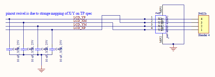
These aren’t so common anymore — it seems like almost everything is capacitive touch nowadays. I wasn’t familiar with the theory of operation behind resistive touchscreens until I wrote this post. Basically there are two transparent resistive layers. One layer goes left and right and the other goes up and down. When you press the touchscreen they connect together. You can calculate the X and Y positions where the layers meet by driving a voltage across one layer and then measuring the voltage of the other layer. Here’s a nice document that does a great job of explaining it in detail.
I have a lot of experience dealing with touchscreens, but it has typically been with USB touchscreens that come with an off-the-shelf touch controller already supported by Linux, such as EETI’s eGalax. You typically just have to make sure you have the correct driver enabled in your kernel config and then it works. Of course, you have to deal with calibrating the touchscreen as well. More on that later.
In this case, there was no simple existing driver in the mainline kernel to enable. Obviously there is an existing driver in Chumby’s old 2.6.28 kernel that we can examine, but first let’s look in more depth at the Chumby’s touchscreen and try to gain a good understanding of how it works. The four signals going to the touchscreen connector are LCD_XM, LCD_XP, LCD_YM, and LCD_YP. Where else do they go on the board?
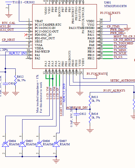
I’ve marked the relevant wires in green. This section of the schematic is the STM32F101 microcontroller which Chumby commonly referred to as the cryptoprocessor. You can see that the four resistive touchscreen wires are going into the microcontroller on PA3, 4, 5, 6, and 7. For some reason, LCD_YP goes to both PA3 and PA5.
Although Chumby’s STM32 firmware was never open sourced as far as I’m aware, bits and pieces of it are definitely visible in the source code for the cpid cryptoprocessor emulator daemon. In particular, this file seems to contain some iteration of the cryptoprocessor’s interrupt handler code. Fortunately, the touchscreen logic is mostly implemented in the SysTick interrupt handler, so the code that handles sampling the touchscreen is intact here. It follows the same general algorithm described by the resistive touchscreen document I linked above with PA4/5/6/7.
I think this code also explains why LCD_YP goes to two pins. I can’t tell for sure because some of the defines are missing, but it looks like PA3 is being used as a normal pulled-up GPIO input for initially detecting whether the screen has been touched. When the screen is idle, PA6 (LCD_XM) is driven to ground and PA4/5/7 (LCD_YM/YP/XP) are left in analog input mode. PA3 (also hooked to LCD_YP) is configured as a pulled-up input. When the screen is pressed, LCD_XM and LCD_YP should connect together which will overcome the internal pullup resistor on PA3 and pull it low. This conveys to the firmware that the screen has been pressed and kicks off the normal touchscreen sampling algorithm.
In the schematic diagram above you can also see the four touchscreen-related SPI signals going into the STM32: TS_MOSI, TS_MISO, TS_SCLK, and TS_CS, along with a fifth TS_TOUCHED signal. These five signals are the interface to the PXA166. This is the part that will be relevant to the Linux driver. On the PXA166 side, TS_TOUCHED goes directly to GPIO_52:
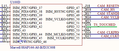
This signal, according to the STM32 code, provides us with quick feedback about whether the touchscreen is currently pressed or not. The nice thing about having this available is we won’t have to be constantly polling the microcontroller over SPI to determine if the touchscreen is pressed. We can just use this pin as a GPIO interrupt to alert us when we need to start paying attention to the touchscreen, and ignore it otherwise.
The SPI signals are a bit more complicated. They go to GPIO_118 through GPIO_121, but those pins are powered by VDD_IO3, which on this particular board is 1.8V instead of 3.3V.
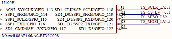
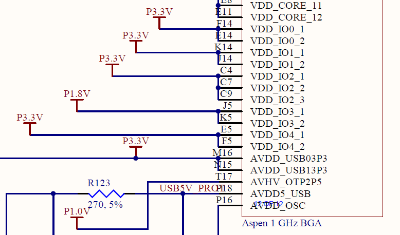
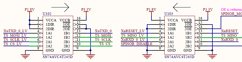
This means that they need to be level shifted in order to connect to the STM32’s 3.3V signals, which is accomplished with a pair of TI SN74AVC4T245 bus transceivers — one for inputs and one for outputs. You can see below that the 1.8V versions of the signals are suffixed with _LV:
Is any of this level shifting stuff or the STM32’s algorithm with the four raw touchscreen wires actually relevant to writing a Linux driver? Probably not, but it’s still a good idea to be familiar with exactly what you’re going to be dealing with before you start writing the software.
So in summary: Linux will talk with the STM32 over SPI. The STM32 will also provide a simple GPIO signal to let us know when the touchscreen is pressed, so we’ll only bother with SPI traffic when we need to. The algorithm on the Linux side will look something like this:
- Wait for TS_TOUCHED to go high. This tells us the touchscreen is pressed.
- Continually poll over SPI to determine the X and Y positions while it’s pressed.
- As soon as TS_TOUCHED goes low, we’re finished and the touchscreen is no longer pressed.
This seems pretty straightforward! Let’s see how it was done in the old 2.6.28 kernel. The driver code is here, or you can download it from Chumby’s tarballs. It seems to be based on another touchscreen driver called s3c-ts.c, but modified for Chumby’s needs. Here’s what the driver does:
- Directly initialize the SSP peripheral in the PXA166 with special register values for “programmable serial peripheral” (PSP) mode that I think was mostly intended for I2S sound stuff, but it’s being used here for SPI. Hook up an IRQ handler that will be called when each transaction completes.
- Register as a touchscreen device.
- Directly set up a GPIO interrupt on GPIO_52 for press detection. Also initialize some other test GPIOs that aren’t necessary for final operation.
- Write to some touchscreen registers over SPI for initialization of various parameters like number of samples, touchscreen released detection threshold, and delays.
- When a touch is detected, activate a 5 ms timer, after which we will commence with SPI transactions.
- Do SPI transactions while the touchscreen is pressed. Request a dump of the registers, and then read back X, Y, and pressure as 16-bit words, one at a time, once per millisecond. Repeat until the touchscreen is no longer pressed. There’s also some error recovery logic if an SPI transfer times out or expected data is never received.
- The STM32 code I inspected above didn’t deal with pressure at all, so I’m assuming it’s something new that was added after the interrupt code bundled with cpid was written.
There is already an SPI driver for the PXA2xx’s SSP controller in mainline Linux: the spi-pxa2xx driver. I suspected that it would be compatible with the PXA166/PXA168 with minimal changes, and it turns out I was correct. I just needed to convey to the driver that the SSP peripherals in this device don’t support clock dividers. I haven’t submitted this fix upstream yet, but I may do so in the future.
Before I bothered to get the SSP controller working with the mainline driver, I wanted to answer a question: why did the Chumby developers use the SSP controller’s PSP mode for SPI communications with the touchscreen? As far as I could tell, the other end (the STM32) was just expecting normal SPI traffic. Would I need to replicate Chumby’s custom approach to configuring the SSP peripheral, as opposed to using the mainline Linux driver that configures it for SPI mode?
I performed a bunch of manual register reads and writes similarly to how I tested out the PWM peripheral in my last post. What I found was if I allowed the SSP controller in the PXA166 to directly control the chip select pin, and I set it up for normal SPI mode, I got back junk data when I tried to read the touchscreen state. I had to use the Chumby driver’s special PSP mode setup in order to get good readbacks of data.
This led me to dig in deeper to understand what the special PSP mode config was doing. As far as I could tell, it was only doing one special thing: it was introducing a 7-clock-cycle delay after chip select was asserted, and before the actual SPI data transaction on SCK/MOSI/MISO began. The purpose was probably to give the STM32 firmware some time in order to prepare a response. I found that if I switched back to normal SPI mode, but controlled the chip select pin manually as a GPIO pin rather than automatically through the PXA166’s peripheral, it also worked fine and gave me good results.
I’m pretty sure this explains why Chumby used the PSP mode in their driver. It was a clever, efficient mechanism for introducing a small chip select delay.
I wanted to do something a bit more standardized and modular with my approach for this driver, even if it meant losing some of that efficiency. Sure, the modularity would be pointless since this touchscreen controller is only used on the Chumby, but I wanted to make use of the existing Linux SPI subsystem which doesn’t have the capability to implement delays through PSP mode. The good news is that Linux has support for software control of the chip select pin as a GPIO, which is exactly what I needed. In fact, I can even specify that the STM32 wants a delay of 7 SCK cycles after CS is asserted by filling out cs_setup in my driver:
spi->cs_setup.value = 7;
spi->cs_setup.unit = SPI_DELAY_UNIT_SCK;
Thinking about this more, it would probably even be possible to update the spi-pxa2xx driver to automatically switch to PSP mode when a cs_setup delay is provided. That would be a lot of work for a pretty small payoff though, so I didn’t go that far. I just stuck with GPIO control of the chip select pin.
I added SSP peripherals to the PXA168 base device tree, and then I hooked up the new touchscreen in my Chumby device tree:
&pinctrl {
	/* Pin config for SSP2 -- touchscreen. Leave CS as normal GPIO so we have
	 * finer control over its timing, at the expense of efficiency. */
	ssp2_pins_default: ssp2default {
		pinctrl-single,pins = <
			MFP_PIN_PXA168(118) MFP_AF1
			MFP_PIN_PXA168(120) MFP_AF1
			MFP_PIN_PXA168(121) MFP_AF1
			MFP_PIN_PXA168(119) MFP_AF0
		>;
	};
};

&ssp2 {
	status = "okay";
	pinctrl-names = "default";
	pinctrl-0 = <&ssp2_pins_default>;
	cs-gpios = <&gpio 119 GPIO_ACTIVE_LOW>;

	spidev@0 {
		compatible = "chumby,chumby8ts";
		reg = <0>;
		spi-max-frequency = <6500000>;
		pendown-gpio = <&gpio 52 GPIO_ACTIVE_HIGH>;
		interrupt-parent = <&gpio>;
		interrupts = <52 IRQ_TYPE_EDGE_RISING>;
		touchscreen-inverted-y;
		touchscreen-swapped-x-y;
	};
};
To explain this in more detail, the pinctrl block above sets all of the SPI pins as alt function 1 except for chip select (GPIO_119) which is set up as alt function 0, also known as GPIO mode, instead.
GPIO_119 gets hooked up as a software chip select controlled through the normal GPIO subsystem using the cs-gpios property. The Chumby touchscreen device, which doesn’t even have a driver yet at this point, is hooked up such that it knows to listen to GPIO_52 to determine if it’s pressed. This connection is made with the pendown-gpio property. You can also see where the rising edge GPIO interrupt for GPIO_52 gets hooked up with the interrupt-parent and interrupts properties. This will alert me with an interrupt when the touchscreen is pressed. Some of the other options like touchscreen-inverted-y and touchscreen-swapped-x-y are self-explanatory standard touchscreen device tree properties that I determined experimentally after I had my driver working.
All of the device tree stuff above is great, but it’s not going to do anything until I have a driver that recognizes the “chumby,chumby8ts” compatible string and all of the properties I’ve specified. To actually implement the driver, I started from the existing mainline ADS7846 SPI touchscreen controller driver. I’ve found that when I develop drivers, starting from something similar seems to be the easiest way to get things working without having to fully understand every intricate detail of the kernel. Luckily in this case, there was an existing SPI touchscreen driver that had similar requirements.
Here’s the new touchscreen driver I implemented. It’s kind of a hybrid between the ADS7846 driver and the old Chumby driver. The ADS7846 driver provided a fantastic example for how to implement an SPI touchscreen controller with a GPIO interrupt in modern kernels, and the old Chumby driver told me what SPI data to send and receive. Given that the existing pattern of SPI transactions used by Chumby’s 2.6.28 driver seemed to work okay, I pretty much just replicated what it did: wait 5 milliseconds after the touch is detected, and then perform a single 16-bit read/write every millisecond until touch is no longer detected. It uses a simple state machine for determining whether to request a new set of data or continue shifting in more data.
I briefly considered implementing something different where I would just try to read all of the data in a big sequence every 5 milliseconds, but I had several concerns about that approach. The SPI communication on the cryptoprocessor was implemented in STM32 firmware, so I had to be careful not to try to read from it too quickly and overwhelm it. After all, I had already witnessed an issue when talking with it too quickly. Also, Chumby’s original driver had some special error recovery stuff going on if it received too many “noop” responses in a row. I didn’t want to mess with the behavior too much because I assumed there had to be a reason Chumby did it that way. I didn’t want to go through the fun of tediously relearning why Chumby had to implement error handling the way they did.
The ADS7846 driver showed me how to make use of a threaded IRQ for handling touch events. You start by requesting a threaded IRQ:
err = devm_request_threaded_irq(dev, spi->irq,
                                chumby8_ts_hard_irq, chumby8_ts_irq,
                                IRQF_ONESHOT, dev->driver->name, ts);
When the touchscreen is pressed, the simple hard interrupt handler chumby8_ts_hard_irq checks to make sure it’s still pressed, and then if so, wakes the thread to do all of the actual work outside of hard interrupt context.
static irqreturn_t chumby8_ts_hard_irq(int irq, void *handle)
{
        struct chumby8_ts *ts = handle;

        return get_pendown_state(ts) ? IRQ_WAKE_THREAD : IRQ_HANDLED;
}
The interrupt thread function chumby8_ts_irq runs until the touchscreen is no longer pressed or the driver is removed. I’m allowed to sleep in this function because it’s no longer in hard IRQ context.
static irqreturn_t chumby8_ts_irq(int irq, void *handle)
{
        struct chumby8_ts *ts = handle;

        /* start in a default state, ensure we don't use any coords from last time */
        ts->state = requesting_state;
        ts->noops_received = 0;
        ts->x = 0;
        ts->y = 0;
        ts->pressure = 0;

        /* Start with a small delay before checking pendown state */
        msleep(TS_POLL_DELAY);

        while (!ts->stopped && get_pendown_state(ts)) {

                /* pen is down, continue with the measurement */
                chumby8_ts_poll_state(ts);

                /* wait until we're stopped or it's time to poll again */
                wait_event_timeout(ts->wait, ts->stopped,
                                   msecs_to_jiffies(TS_POLL_PERIOD));
        }

        if (ts->pendown && !ts->stopped)
                chumby8_ts_report_pen_up(ts);

        return IRQ_HANDLED;
}
Essentially the thread reads a 16-bit word, processes it, sleeps for a millisecond, and repeats over and over until you take your finger off of the touchscreen. At that point, the interrupt is finally considered handled. Using a threaded IRQ really cleaned up the code, in my humble opinion anyway!
The chumby8_ts_poll_state function is far too long to share here, but it’s in charge of all communication with the STM32. As soon as it has received a full set of data, it calls chumby8_ts_report_state which forwards the received touchscreen coordinates onto the input subsystem as BTN_TOUCH, ABS_X, ABS_Y, and ABS_PRESSURE readings. The ABS_X and ABS_Y readings are fed in through the common touchscreen_report_pos helper function to allow any device tree inverted/swapped properties (such as the ones in my example above) to be applied first.
static void chumby8_ts_report_state(struct chumby8_ts *ts)
{
        struct input_dev *input = ts->input;
        if (!ts->pendown) {
                input_report_key(input, BTN_TOUCH, 1);
                ts->pendown = true;
        }

        touchscreen_report_pos(input, &ts->core_prop, ts->x, ts->y, false);
        input_report_abs(input, ABS_PRESSURE, ts->pressure);
        input_sync(input);
}
After the touchscreen is no longer pressed, chumby8_ts_report_pen_up sends out a final update showing BTN_TOUCH released and zero pressure.
static void chumby8_ts_report_pen_up(struct chumby8_ts *ts)
{
        struct input_dev *input = ts->input;

        input_report_key(input, BTN_TOUCH, 0);
        input_report_abs(input, ABS_PRESSURE, 0);
        input_sync(input);

        ts->pendown = false;
}
By the way, these different input codes were registered with the input subsystem earlier during device probe:
input_set_capability(input_dev, EV_KEY, BTN_TOUCH);
input_set_abs_params(input_dev, ABS_X, 0, MAX_12BIT, 0, 0);
input_set_abs_params(input_dev, ABS_Y, 0, MAX_12BIT, 0, 0);
input_set_abs_params(input_dev, ABS_PRESSURE, 0, MAX_12BIT, 0, 0);
After implementing the driver and recompiling my kernel, it showed up as an input device!
[    4.701879] chumby8_ts spi0.0: touchscreen, irq 132
[    4.707096] input: Chumby 8 touchscreen as /devices/platform/soc/d4000000.apb/d401c000.spi/spi_master/spi0/spi0.0/input/input0
I tested it out with the evtest utility:
# evtest /dev/input/event0
Input driver version is 1.0.1
Input device ID: bus 0x1c vendor 0x0 product 0x0 version 0x0
Input device name: "Chumby 8 touchscreen"
Supported events:
  Event type 0 (EV_SYN)
  Event type 1 (EV_KEY)
    Event code 330 (BTN_TOUCH)
  Event type 3 (EV_ABS)
    Event code 0 (ABS_X)
      Value      0
      Min        0
      Max     4095
    Event code 1 (ABS_Y)
      Value      0
      Min        0
      Max     4095
    Event code 24 (ABS_PRESSURE)
      Value      0
      Min        0
      Max     4095
Properties:
Testing ... (interrupt to exit)
When I touched the screen and dragged my finger across it, I got the following output from evtest:
Event: time 1656962454.055399, type 1 (EV_KEY), code 330 (BTN_TOUCH), value 1
Event: time 1656962454.055399, type 3 (EV_ABS), code 0 (ABS_X), value 3418
Event: time 1656962454.055399, type 3 (EV_ABS), code 1 (ABS_Y), value 1979
Event: time 1656962454.055399, type 3 (EV_ABS), code 24 (ABS_PRESSURE), value 685
Event: time 1656962454.055399, -------------- SYN_REPORT ------------
Event: time 1656962454.135372, type 3 (EV_ABS), code 0 (ABS_X), value 3391
Event: time 1656962454.135372, type 3 (EV_ABS), code 1 (ABS_Y), value 1938
Event: time 1656962454.135372, type 3 (EV_ABS), code 24 (ABS_PRESSURE), value 708
Event: time 1656962454.135372, -------------- SYN_REPORT ------------
Event: time 1656962454.215375, type 3 (EV_ABS), code 0 (ABS_X), value 3216
Event: time 1656962454.215375, type 3 (EV_ABS), code 1 (ABS_Y), value 1827
Event: time 1656962454.215375, type 3 (EV_ABS), code 24 (ABS_PRESSURE), value 696
Event: time 1656962454.215375, -------------- SYN_REPORT ------------
Event: time 1656962454.295397, type 3 (EV_ABS), code 0 (ABS_X), value 3014
Event: time 1656962454.295397, type 3 (EV_ABS), code 1 (ABS_Y), value 1765
Event: time 1656962454.295397, type 3 (EV_ABS), code 24 (ABS_PRESSURE), value 713
Event: time 1656962454.295397, -------------- SYN_REPORT ------------
Event: time 1656962454.375379, type 3 (EV_ABS), code 0 (ABS_X), value 2790
Event: time 1656962454.375379, type 3 (EV_ABS), code 1 (ABS_Y), value 1787
Event: time 1656962454.375379, type 3 (EV_ABS), code 24 (ABS_PRESSURE), value 720
Event: time 1656962454.375379, -------------- SYN_REPORT ------------
Event: time 1656962454.455397, type 3 (EV_ABS), code 0 (ABS_X), value 2572
Event: time 1656962454.455397, type 3 (EV_ABS), code 1 (ABS_Y), value 1868
Event: time 1656962454.455397, type 3 (EV_ABS), code 24 (ABS_PRESSURE), value 717
Event: time 1656962454.455397, -------------- SYN_REPORT ------------
Event: time 1656962454.535372, type 3 (EV_ABS), code 0 (ABS_X), value 2305
Event: time 1656962454.535372, type 3 (EV_ABS), code 1 (ABS_Y), value 1891
Event: time 1656962454.535372, type 3 (EV_ABS), code 24 (ABS_PRESSURE), value 683
Event: time 1656962454.535372, -------------- SYN_REPORT ------------
Event: time 1656962454.615381, type 3 (EV_ABS), code 0 (ABS_X), value 1959
Event: time 1656962454.615381, type 3 (EV_ABS), code 1 (ABS_Y), value 1832
Event: time 1656962454.615381, type 3 (EV_ABS), code 24 (ABS_PRESSURE), value 672
Event: time 1656962454.615381, -------------- SYN_REPORT ------------
Event: time 1656962454.675251, type 1 (EV_KEY), code 330 (BTN_TOUCH), value 0
Event: time 1656962454.675251, type 3 (EV_ABS), code 24 (ABS_PRESSURE), value 0
Event: time 1656962454.675251, -------------- SYN_REPORT ------------
That looks pretty good! It is detecting the press, some movement, and then finally the release. I’ve also noticed that if I press harder on the touchscreen it increases the ABS_PRESSURE value, so there is definitely some extra stuff going on to detect touch pressure in the Chumby 8’s STM32.
I haven’t submitted this driver upstream yet, so I don’t know for sure if this is the 100% correct way to do it. It seems to work for me, and the ADS7846 driver uses a similar approach, so that would be in my favor. If I submitted it, I would definitely need to add documentation in the Documentation/devicetree/bindings directory first — I haven’t bothered with that yet. The thought of submitting this to the mainline kernel also slightly worries me — I don’t want to defend decisions about the SPI transaction timing and error handling that I don’t fully understand. But hey, it works!
With this driver completed, I wasn’t quite done yet though. I needed a way to calibrate the touchscreen, and I also had a choice to make about which method to use in order to hook the touchscreen up to X11. Remember that I’m stuck with X11 due to the 2D graphics accelerator not being supported by newer technologies.
Let’s look at the different ways you can use touchscreens on Linux first. In the past I have used tslib, but you shouldn’t really need tslib with normal Linux input devices, unless you need to make use of some of its fancy filtering options. Another option is to just read from it as a normal Linux event device using the Xorg evdev plugin. The evdev plugin has an “Evdev Axis Calibration” property you can use to calibrate it. Alternatively, you can directly calibrate Linux event devices by modifying the minimum and maximum absolute values on the ABS_X and ABS_Y axes, but that feels kind of hacky.
What I settled on was libinput, which seems to be the direction a lot of people have been going for using input devices with modern software. I think it will be more future-proof. It worked out of the box with my driver, but obviously the touchscreen calibration was wrong, so I needed a way to calibrate it.
Let’s talk about touchscreen calibration. I’ve mentioned it a few times in this post, but I haven’t explained it. I think some modern touchscreens don’t need calibration, but it was definitely a common problem back in the heyday of resistive touch panels. The problem is that although the Chumby’s touch controller returns values between 0 and 4095 for both the X and Y axes, it turns out that only a portion of that range is used. On my Chumby, the left side of the screen maps to an X value of 223 and the right side of the screen is 3774. The usable Y range is 370 to 3733. If you don’t calibrate the touchscreen, you will find that touches on the screen don’t correctly map to the pixels corresponding with the touch location.
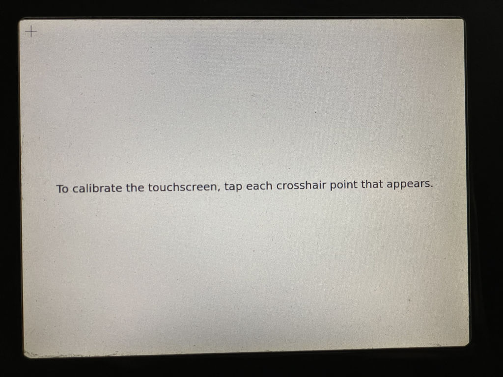
Typically this is solved with a utility that tells you to tap on a few known locations on the screen. It’s common to see 4- and 5-point calibration routines. The utility then calculates a calibration matrix that is applied to every raw reading from the touchscreen to transform it into a usable pixel location on the display.
I found it incredibly frustrating to research how to calibrate touchscreens with libinput. It seems like a lot of the existing tools out there are designed for older mechanisms like evdev. Everyone talks about using xinput_calibrator, but I don’t think it’s designed to work with libinput. I saw a few pull requests for libinput support, so it’s possible that somebody’s fork would have helped get things working.
For this project, I wasn’t bothered by the lack of available tools. The way I see it, existing touchscreen calibration apps are nice to have available, but you also need the ability to integrate it into your own program if you want complete control over what the GUI will look like during the calibration process. So I made my own basic touchscreen calibration utility for the Chumby called Chumby8TSCal. I’m so good at coming up with creative names, aren’t I?
I’m definitely not a touchscreen calibration math expert, and I didn’t want to spend too much time figuring it out because I didn’t think I needed anything fancy for this. I opted to implement a super basic 4-point calibration routine for now, with no support for rotation or skewing. You tap known locations on each of the four corners of the screen, and then my utility calculates a simple transformation matrix to use.
One thing I want to point out is that libinput normalizes the coordinates before applying its calibration. This is different from other calibration schemes I’ve seen in the past. So instead of feeding raw touchscreen coordinates of 0 to 4095 into my calibration matrix, it gives me normalized coordinates of 0.0 to 1.0, where in the case of this driver 0.0 maps to a raw value of 0 and 1.0 maps to a raw value of 4095. My calibration matrix is expected to transform these normalized 0.0 through 1.0 input values into normalized screen coordinates instead, where 0.0 represents the left/top side of the screen and 1.0 represents the right/bottom side of the screen. I found this super confusing at first, but I figured it out with some trial and error. Scaling the coordinates to the display resolution in pixels happens later and is outside of the scope of this calibration. This approach used by libinput makes a lot of sense to me, because if you have a monitor that can display multiple resolutions, the normalized calibration will be correct regardless of the resolution currently being displayed.
You can apply the new calibration matrix live inside of Xorg using the XChangeDeviceProperty function of libXi. You can also save the calibration matrix so that Xorg automatically applies it at startup with a config file like this in /etc/X11/xorg.conf.d:
Section "InputClass"
    Identifier "touchscreen"
    MatchIsTouchscreen "TRUE"
    MatchDriver "libinput"
    Option "CalibrationMatrix" "1.153196283 0.0 -0.062799211 0.0 1.217662801 -0.110020815 0.0 0.0 1.0"
EndSection
My calibration program provides examples of both of these approaches. If you are interested in looking at my code for this, I will warn you in advance that Xlib’s API is a tad bit on the confusing side. For example, I have to set a custom error handler with XSetErrorHandler() in order to detect errors, because the actual functions that do the operations don’t necessarily return errors immediately. I guess this is due to the fact that the X server might be a remote computer somewhere and it’s not feasible to block until we know the result, but it definitely makes it more complicated than it sounds to change the calibration matrix live. After researching this some more while writing this post, it looks like I should have used XCB instead!
Anyway, the end result is I have a simple program that you run once on the Chumby to calibrate the touchscreen. It applies the new calibration immediately and saves it for future powerups. I haven’t cleaned this up and made it something that automatically runs in response to some kind of recalibration action (maybe holding your finger down on the screen at bootup?), but I feel like that would be simple to implement. It would be nice to give it a prettier UI too.
Compared to some of the previous shenanigans I’ve dealt with during this project, the touchscreen really wasn’t too bad. That’s not to say that it was easy. After all, I had to create a new driver. But the overall process was straightforward and I didn’t run into any crazy roadblocks or showstopper hardware bugs. This was pretty much just a direct modernization port and cleanup of the old driver.
With this new touchscreen driver in place, the screen is now fully operational in my modern kernel. This leaves the Chumby in a pretty good state for being ready to run some little apps that I create in the future. There is one big thing that’s still missing, though: audio. In the next part, I’ll delve into the process of figuring out how to play sound through the speakers.


Thanks for continuing with this series- great to learn about resistive touchscreens.
Glad you’re enjoying it, Steve!
I bought my Chumby8 some 10+ years ago planning to turn it into a testbed for embedded development for a project but besides an occasional cross-compilation I never progressed far. Meanwhile, the device has been in continuous use through the years and its longevity coupled with obscure story of the parent company and commitment to keep the service running, when so many other IoT companies shut their lights off, has accumulated a mass of good will towards the little slugger.
Thanks for bearing the torch, your series is incredibly insightful and I eagerly await each new post!
Thanks Oleg! Hopefully I won’t keep you waiting too long for the next one; the audio support will be a lot to write about!
I bought my Chumby 8 from Woot for a similar reason back in 2011, but never really set it up or used it as intended. It sat in a desk for a decade. I’m impressed that you’re still using yours!
I can’t make any promises that this series will end up as anything usable out of the box for people, but at the very least, I hope it’ll provide other tinkerers with a toolset to start from.
Thank you for continuing with this! I also have some Chumbys from Woot.
I also have a Dash whose wifi card just stopped working, so I’m looking at putting a new kernel and distribution on it to see what’s going on. I’m following this series with interest!
Thanks Ben! This series definitely isn’t over, it’s just taking me a while to get around to writing the next post.
[…] upgrade saga (here are links to parts 1, 2, 3, 4, 5, 6, and 7), I really felt like I was starting to reach the finish line. The display was working well enough […]