In the previous post in this series (here are links to parts 1, 2, 3, 4, and 5), I really got the Chumby to start looking like a Chumby. The display was alive! But getting the LCD controller working was really only one puzzle piece when it came to the display. The backlight needed more work so that I could control the brightness, and the touchscreen controller is a completely nonstandard design that is specific to the Chumby.
Let’s start with the backlight. This should be pretty straightforward, right? Looking at the schematics, the backlight control is connected to GPIO_84 (also known as PWM_OUT1) on ball A4 of the PXA166. I already knew that I could turn the backlight on full blast by using this pin as a normal GPIO pin and driving it high. That’s what I did in the previous post in order to quickly get it working.
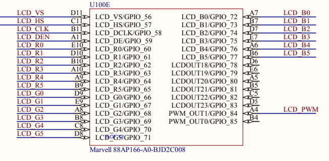
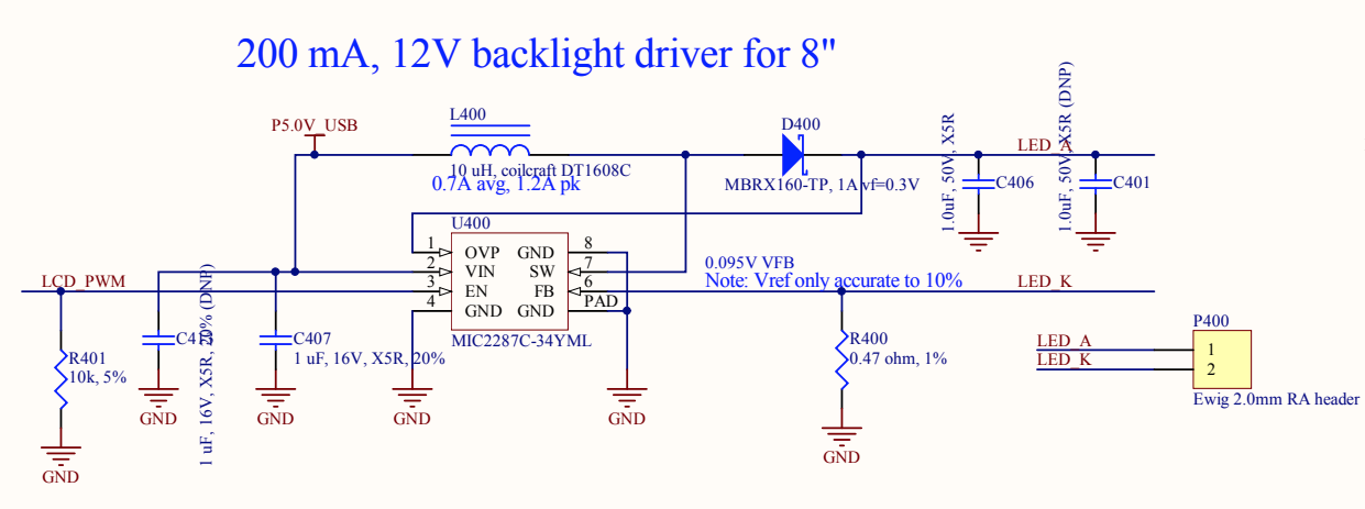
Understanding this circuit is honestly way beyond my knowledge level, but it was pretty clear based on the name of the signal (LCD_PWM) that this was my brightness control. The MIC2287C is an LED driver. You’re supposed to supply a PWM signal on the EN pin to dim the backlight. For anyone not familiar with PWM, it stands for pulse-width modulation. The basic idea is that the pin will be rapidly changing between high and low states. The more time the pin stays high as opposed to low, the brighter the backlight will be.
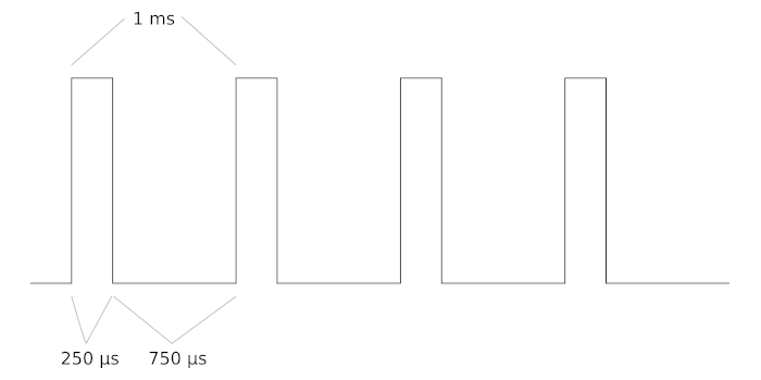
You could do this by manually toggling the GPIO pin in software with time delays, but that would be insane, imprecise, and needlessly waste your CPU cycles. That’s why you want to use a PWM peripheral built into the processor that can handle it for you in the background with zero cost to the CPU. You just control two settings: frequency and duty cycle. The frequency is how many times per second the controller outputs a complete cycle, and the duty cycle is the percentage of the time the pin should stay high in each cycle. For example, a 100% duty cycle means the pin is always high. A 25% duty cycle means the pin is high for 1/4 of the time and low the other 3/4 of the time. Here’s an example of a 1 kHz PWM signal with a 25% duty cycle:
I started out by trying to figure out how to use the PWM peripheral in the PXA166. One strategy I like to follow with really simple stuff like PWM is just manually do the register writes and prove the concept by hand. This turned out to be a really smart decision because this PWM controller has some really funky issues.
I looked at the alternate functions supported on ball A4 (GPIO_84). The software manual says that its pad control register is 0xD401E150, and the supported alternate functions are:
- 0 = GPIO_84
- 2 = PWM2
- 3 = ONE_WIRE
- 4 = PWM1
- 7 = EXT_32K_IN
The bolded entries in the list above are the ones relevant to me. I could set it as PWM1 or PWM2. One thing that’s always fun about numbering on stuff like this is you never know if the peripherals are zero-indexed or one-indexed, meaning: is PWM1 the first PWM peripheral or the second one? The answer in this case is PWM1 is the first, so it’s one-indexed.
I chose to use alt function 2 = PWM2 because that’s the peripheral that the original Chumby kernel used. The Chumby kernel’s backlight control code didn’t use the common PWM subsystem and instead was its own driver that controlled the PWM peripheral directly by writing to its registers. It’s possible that was the normal way to do it back in the Linux 2.6.28 days. I’m not sure. Maybe they ran into some of the same problems I did and wrote their own driver in order to not have to deal with them. Anyway, the first step was to set GPIO_84’s alt function to 2:
mw.l 0xd401e150 0x00000842
This sets it for pullups/pulldowns disabled, 2x drive strength, an undocumented bit that U-Boot calls MFP_LPM_EDGE_NONE, and alternate function 2. I was just following the pattern of how a bunch of the pads were set up in U-Boot. As soon as I ran this command, the screen turned black. This makes sense, because it was no longer controlled by the GPIO peripheral and I didn’t have the PWM controller enabled yet.
Next, I tried to enable the PWM controller. This is where the fun began. I found that the clock for PWM2 is controlled by the PWM2 Clock/Reset Control register at 0xD4015010. Bit 0 is reserved (which I found odd), bit 1 should be 1 to turn on the functional clock, and bits 6:4 choose whether you want a 13 MHz or 32 kHz clock for the PWM. I chose 13 MHz (bits 6:4 = 0) and tried to turn it on:
mw.l 0xd4015010 0x02
This still didn’t do anything, but that’s normal because I hadn’t actually set up the PWM controller with a period and duty cycle yet. This required some thinking about what frequency to use. The MIC2287C datasheet said that typical PWM frequencies would be between 100 Hz and 10 kHz. I opted to try 2 kHz at first. The PWM controller is pretty simple. Each controller has three 32-bit registers:
- 0x0000 – PWMx_CR – Control register
- Contains a 6-bit prescaler allowing you to divide the incoming clock by 1 to 64
- Also has a shutdown mode flag to decide if the PWM should stop abruptly when you turn it off or finish the last cycle first. More on this later.
- 0x0004 – PWMx_DCR – Duty cycle register
- Contains a 10-bit duty cycle allowing you to set a period of 0 to 1023 scaled clock cycles, as well as a flag for “always 100%” which together effectively act as an 11-bit duty cycle supporting the values 0 to 1024.
- 0x0008 – PWMx_PCR – Period control register
- Contains a 10-bit period field allowing you to set a period of 1 to 1024 scaled clock cycles
As a plan of attack, I tried to get a 100% duty cycle working with a frequency around 2 kHz. The frequency doesn’t really matter when you have the duty cycle set to 100%, but it will come into play once I try to dim the screen. With an incoming clock of 13 MHz, dividing it by the maximum divider of 64 results in a scaled frequency of 203.125 kHz, which also means 4.923 microseconds per clock cycle. In order to get a 2 kHz PWM frequency from that, I would need each cycle to be 500 microseconds long. Doing the math on this (203125/2000), I would want to use a period of 101 or 102 (102 is closer) clock cycles. I opted for 102, so I wrote a value of 101 = 0x65 into the PWMx_PCR register. The reason I wrote 101 instead of 102 is because the value in the register is one less than the requested period; a value of 0 means a period of 1 clock cycle.
For a duty cycle of 100%, I simply needed the duty cycle period to be 102, so I wrote a value of 102 = 0x66 into the PWMx_DCR register. It doesn’t have the same offset by 1 that the period control register has because 0 is a valid duty cycle.
To give the clock the maximum prescaler of 64, I wrote 63 = 0x3F into the PWMx_CR register, ignoring the abrupt shutdown bit for now.
As a summary, here are the U-Boot commands to write those values into PWM2 which is mapped at 0xD401A400:
mw.l 0xd401a400 0x3F
mw.l 0xd401a408 0x65
mw.l 0xd401a404 0x66
I anxiously typed these in, and…of course, it didn’t work. Because why would anything work on the first try?
I delved further into the datasheet and realized that PWM1 and PWM2 shared some common clock and reset bits in PWM1’s clock control register at 0xD401500C, similar to what I ran into with the SDHC controllers in part 2. Remember when I was suspicious that bit 0 was reserved in PWM2’s clock control register? Well, I was onto something. That bit is the shared APB bus clock enable for PWM1/PWM2 in PWM1’s version of the register. Bit 2 in PWM1’s register is also shared between both — it’s the shared reset bit which should be set to 0. The datasheet didn’t say anything in PWM2’s section about “Hey, check the PWM1 register for some important bits”. Sigh. This is a perfect example of the life of an embedded software engineer!
Back to the U-Boot console: this meant I also needed to enable the shared APB clock in PWM1’s clock control register:
mw.l 0xd401500c 0x1
I was confident at this point that this would fix everything. Everything related to PWM2 was enabled, including the shared PWM1 requirements. A good PWM period, duty cycle, and prescaler were programmed in. But the dang thing still wouldn’t work.
After scratching my head and experimenting more, I tried switching to PWM1 instead. My thought process was maybe something weird was going on with PWM2, and the pin also supported being configured as PWM1, so I might as well try that peripheral instead.
mw.l 0xd401e150 0x00000844
mw.l 0xd401500c 0x00000003
mw.l 0xd401a000 0x3F
mw.l 0xd401a008 0x65
mw.l 0xd401a004 0x66
To my surprise, when I configured it as PWM1 using the commands above, the backlight turned on. It worked perfectly!
I could have just told myself “that’s good enough” and switched to using PWM1 but I’m too stubborn. I knew PWM2 was supposed to work and the Chumby kernel had also used it, so I wanted to get PWM2 working. With the unit still powered on, I retraced all of my steps and reconfigured everything for PWM2. This time, PWM2 was working exactly as intended! WTF? I hadn’t changed any of my setup steps!
Long story short, after more tinkering I discovered that the PWM2 peripheral doesn’t work until you enable PWM1’s functional clock, even though the datasheet doesn’t say anything about PWM1’s functional clock enable bit affecting PWM2 in any way. All you have to do is enable PWM1’s functional clock for a brief moment and then turn it back off. PWM2 will continue to work correctly from that point forward. I also found that bit 2 of PWM2’s clock control register, which is marked as reserved and should always be written as 0, actually defaults to 1, so it needs to be written as 0 at some point or else it won’t work. I added a quick hack in U-Boot to go through this sequence to “unlock” PWM2 so I would never have to worry about it again. I never found any kind of errata document mentioning this issue, although I did end up noticing that Chumby had to do a similar hack in their kernel. Their hack accomplishes the same thing as mine, although they left the PWM2 functional clock on forever, and they also refer to them as 0 and 1 instead of 1 and 2 [the “sic” is theirs, not mine]:
    /*
     * Bring PWM0 and PWM1 (sic) out of reset.
     * Not sure why both are required.
     */
    __raw_writel(3, APBC_PXA168_PWM0);
    __raw_writel(3, APBC_PXA168_PWM1);
Now that we’ve gotten out of that rabbit hole, I can continue talking about actually getting PWM working. As a reminder, after enabling the clocks and reconfiguring the GPIO function, these were the U-Boot commands I ran to configure PWM2 with 100% duty cycle at about 2 kHz:
mw.l 0xd401a400 0x3F
mw.l 0xd401a408 0x65
mw.l 0xd401a404 0x66
This was working fine. Next, I tried a 50% duty cycle:
mw.l 0xd401a404 0x33
It worked! The screen dimmed! But I could hear a faint high-pitched buzzing sound. That would be super annoying to listen to. It also wasn’t very surprising in hindsight. I tried a lower frequency of 200 Hz instead. Repeating a similar calculation (203125/200 = 1016-cycle period) led me to the following register values for about 200 Hz with a 50% duty cycle:
mw.l 0xd401a408 0x3F7
mw.l 0xd401a404 0x1FC
This time I still had a dimmed screen but I didn’t hear any buzzing anymore. I also couldn’t see any flickering, so it wasn’t too slow either. Success! I could change the backlight brightness by tweaking the value written to the duty cycle register. It’s kind of hard to tell in the picture below, but trust me, it works! My phone’s camera can definitely see flickering on the screen when the backlight is below 100%, but my eyes can’t see it.

I felt confident I could now set up a PWM backlight in Linux. By the way, I later double checked and verified that this seems to also be about the same frequency that the Chumby developers originally decided on — the old kernel’s backlight driver was coded to select the slowest possible PWM frequency: 13 MHz / 64 / 1024 = 198.364 Hz.
I found a driver in Linux that already supports this hardware. It’s called pwm-pxa and it supports the PWM controller in several other PXAxxx variants as well. So with that in mind, I theoretically would just need to enable the module in my kernel config and hook it up in the device tree. Since the PXA168’s base dtsi file was pretty barebones, I added all of the PWM peripherals and hooked up the clocks. Here’s an example for the pwm2 peripheral:
pwm2: pwm@d401a400 {
	compatible = "marvell,pxa168-pwm";
	reg = <0xd401a400 0x10>;
	#pwm-cells = <1>;
	clocks = <&soc_clocks PXA168_CLK_PWM1>;
	resets = <&soc_clocks PXA168_CLK_PWM1>;
	status = "disabled";
};
Note that the clock defines for the PXA168 are zero-indexed, hence why I use PXA168_CLK_PWM1 instead of PXA168_CLK_PWM2.
In my dts file, I just had to enable it and hook it up as a PWM backlight:
/ {
reg_backlight: regulator-backlight {
compatible = "regulator-fixed";
regulator-name = "backlight-fixed-supply";
regulator-min-microvolt = <12000000>;
regulator-max-microvolt = <12000000>;
regulator-always-on;
};
backlight: backlight {
compatible = "pwm-backlight";
pinctrl-names = "default";
pinctrl-0 = <&pwm2_pins_default>;
/* 5,000,000 nanoseconds = 200 hz */
pwms = <&pwm2 5000000>;
power-supply = <®_backlight>;
status = "okay";
brightness-levels = <0 4 8 16 32 48 64 96 128 192 255>;
default-brightness-level = <5>;
};
};
&pinctrl {
pwm2_pins_default: pwm2default {
pinctrl-single,pins = <
MFP_PIN_PXA168(84) MFP_AF2
>;
};
};
&pwm2 {
status = "okay";
};
You may notice that I tweaked the brightness levels to make it feel more linear. Also, the pinctrl stuff allows me to leave it set as a GPIO in U-Boot with full brightness, and then as soon as the kernel loads, it changes to the PWM2 alt function and defaults to a value that I considered to be 50% brightness.
The kernel’s menuconfig wouldn’t even let me enable the driver (CONFIG_PWM_PXA=y) until I patched Kconfig to allow it on the MMP platform. I also enabled the PWM backlight and fixed-voltage regulator drivers:
CONFIG_REGULATOR_FIXED_VOLTAGE=y
CONFIG_BACKLIGHT_PWM=y
Now this story is done and we’re ready for the next part, right?
Nope. This freaking PWM peripheral gave me even more headaches once I started working with it inside of Linux. I booted up Linux with my modified device tree and the backlight immediately turned off.
It appeared that Linux was doing valid writes to the peripheral and trying to set the correct duty cycle, but the PWM controller was getting mad and shutting off the functional clock. What I ended up discovering was that the pxa_pwm_apply() function in the Linux driver was turning the peripheral on, off, and on again when it first tried to enable the PWM. Turning the PWM clock off and immediately back on too quickly resulted in it staying off indefinitely.
I worked around this issue in the driver by changing the sequence of events so it wouldn’t turn the PWM clock off while reconfiguring if it was already on. This allowed the backlight to actually stay on at boot, and I could change the brightness by writing values between 0 and 10 in sysfs!
echo 10 > /sys/class/backlight/backlight/brightness
echo 0 > /sys/class/backlight/backlight/brightness
echo 5 > /sys/class/backlight/backlight/brightness
While playing with this, I noticed that sometimes when I wrote a value of 0 for the brightness, the backlight wouldn’t shut off. It would just stay on full blast. This was more likely to occur when starting from higher brightnesses. I determined that if the PWM pin happened to be high when the clock was shut off, the pin would just stay high forever. This was an easy workaround in the driver: write a value of 0 for a duty cycle prior to disabling the clock. That seemed to fix it.
The process of upstreaming these changes was fantastic. Despite the frustration of working with this peripheral, I had so much fun working on this driver. Uwe Kleine-König, who is the designated reviewer for the PWM subsystem, was great to work with. Uwe provided excellent feedback and gave me some suggestions on how to clean up the existing code and arrange everything in a better way. You can see the three revisions of my patch series here [V1], here [V2], and here [V3].
One thing Uwe pointed out was that the driver should have been writing a value of 0 to the duty cycle register prior to disabling the clock anyway. If you don’t write a 0 before turning it off, the next time you turn it on you will immediately get a new cycle of the existing setting even if you are trying to start it back up with a different duty cycle and/or frequency. This probably isn’t a huge deal for PWM backlights where you wouldn’t be able to tell the difference for one cycle, but it would definitely matter in other applications.
Unfortunately after reorganizing based on Uwe’s suggestions, I still ran into a problem where an on->off->on transition would cause the PWM controller to shut off unexpectedly. I tried working around it with a timer delay to ensure the driver wouldn’t turn the clock back on until enough time had elapsed such that the last PWM cycle would have already completed. It worked, but it felt pretty hacky.
So instead, we settled on using the abrupt shutdown mode in bit 6 of the control register to stop the PWM cycle immediately when you turn it off, rather than allowing it to complete. The graceful shutdown functionality seemed to be the main cause of the issue. With graceful shutdown enabled, if I turned the PWM clock back on while it was in the middle of a graceful shutdown, the graceful shutdown would turn the clock back off when it completed even though Linux thought it was still on. Switching to abrupt shutdown mode mostly worked around it.
I say “mostly” because there is still one issue. If the backlight is already on, and I quickly turn it off and on immediately with the following command:
echo 0 > /sys/class/backlight/backlight/brightness ; \
echo 10 > /sys/class/backlight/backlight/brightness
…then sometimes the display shuts off. It happens about 50% of the time. If you add a tiny, tiny delay between these two writes then everything is fine. So basically, the abrupt shutdown mode change made it much less likely to occur, but it still can happen. I think with abrupt mode there is still a small graceful shutdown happening behind the scenes. It may only be one PWM clock in length.
I was sick of dealing with the PWM driver by now though, so I considered it an edge case and didn’t worry about it. You would have to intentionally toggle the backlight on and off very rapidly to actually run into this problem in practice. I don’t think it’s fixable without adding an ugly delay somewhere. It seems to be a weird design quirk in the PXA16x where the PWM controller has the ability to shut off its own clock enable bit behind Linux’s back. Anyway, as long as I prevent that quick sequence from happening in any userspace software I write, it shouldn’t be an issue for this project.
Whew! This should have been easy, but I ran into a few issues with Marvell’s PWM IP and the kernel driver. I’m glad it’s behaving well enough now. My fixes for the pxa-pwm driver were released with Linux 6.2 earlier this year.
I wanted to talk about the touchscreen in this post as well, but it got too long because I forgot about how many problems I ran into while getting PWM working. The touchscreen will be the topic of the next post, and that should conclude the display portion of the series. There’s still a lot more to cover, so stay tuned!


[…] Doug Brown ☛ Upgrading my Chumby 8 kernel part 6: PWM backlight […]