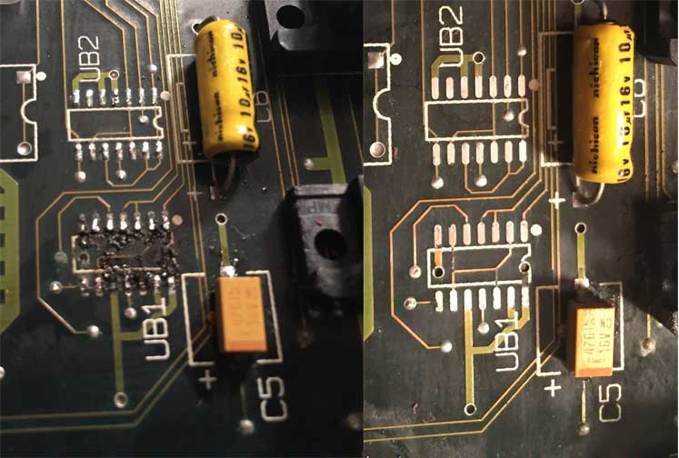
I recently repaired a Macintosh IIx I bought on eBay. It wouldn’t power on at all–both the rear power button and the keyboard power button did nothing. I was already aware that this system needs fresh batteries in order to boot, and I had removed the old batteries and replaced them with new ones, which didn’t make a difference. The real culprit: all of the surface-mount aluminum electrolytic capacitors had leaked electrolyte all over the logic board. This is a very common problem in older computers. These capacitors have a nasty habit of leaking after about 20 years or so. The electrolyte ate away at traces and several traces near capacitors were broken. Several IC pins were corroded really bad as well and had lost contact to their solder pads.
It was quite a journey figuring out how to fix it. The power button didn’t do anything, so I didn’t have a clue where to look. Luckily, an important figure in the Classic Mac community, Gamba, created a schematic of the power circuit. Sadly, Gamba passed away, but his site is still operational (update 4/5/2019: his site was finally taken down, but I updated the links to point to archive.org). I think there is a small error in his schematic, so I went ahead and fixed it. The fixed schematic is depicted below. The only change is the positioning of J18-15 and TS1 on the right side:
I began looking at this schematic and realized I didn’t have a clue what was going on in any of it. All of those NAND gates, diodes, and transistors looked intimidating. I buckled down and did my best to read the schematic and figure out what every piece does. After lots of experimentation and research, I feel like I understand this circuit pretty well now. I’ve decided to write this post to help explain the circuit and maybe help people in the future who are trying to figure out why their II/IIx won’t start up. Note: I am not an electronics expert. I’m trying my best, but I could be wrong about some details. Corrections would be appreciated!
Note that the diagram’s component numbering is for the Mac II. The IIx is slightly different. I would provide more detail, except my IIx logic board is a prerelease one that has the same component numbering as the II. So my IIx’s logic board’s component numbering matched this diagram. Other IIx systems do not match. [Update 6/28/2025: David Cook on the 68kMLA forums has discovered that earlier Mac II motherboards have a slightly different setup with the power off portion of the circuit, so be sure to check his post out for more details on that].
Let’s get started!
Overview
Here’s a broad overview of the different pieces of the circuit:
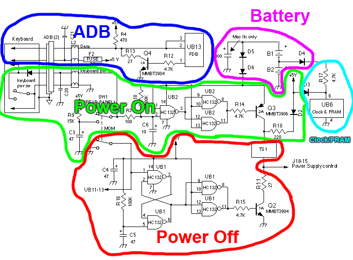
The ADB portion of this circuit is unrelated to this discussion, so I will skip it. Don’t worry–I have included the keyboard power button as part of my description of the power on circuit.
When I first looked at this diagram, for some reason I thought the top half was for the keyboard and the bottom half was for the rear power button. I was totally wrong. The keyboard and rear power button share most of the same power on circuitry. Now, I’m going to cover each section in more detail.
Batteries
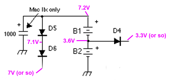
The two batteries B1 and B2 (3.6V 1/2 AA lithium) are in series with each other. This means they combine together to create a 7.2V voltage across ground and the positive terminal of B1. [Edit: Lee Carter pointed out in the comments below that the original batteries are actually 3V 1/2 AA, so they would actually total together to be 6V. You can correct the voltage numbers in the pictures and description below based on this new information] The three diodes seem to serve two purposes:
- Drop the voltage a little bit
- Protect against reverse polarity (putting the batteries in backwards)
In particular, D5 and D6 take the 7.2V voltage from the batteries and drop it down to about 7V or so. Normally these diodes would have a higher voltage drop, but you will see that while sitting idle, there isn’t much current being drawn from them, so the diode voltage drop is pretty low. D4 drops the 3.6V voltage a little bit, but I think its main purpose is to protect against reverse polarity. If you put B1 and B2 in backwards, D4 and D5 will prevent negative voltages from making their way to any other part of the logic board.
The 1000 μF capacitor is (I believe) the capacitor on the battery replacement board, and it can be found on both the II and the IIx, despite what Gamba’s diagram says. These computers originally came with the two batteries soldered directly to the logic board. When they needed to be replaced, there was a little circuit board that a service provider would solder on to replace the original batteries. It had two battery holders and a 1000 μF capacitor. I don’t fully understand the purpose of the capacitor, but it might be to make life easier on the batteries when the power button is pressed.
So this portion of the circuit takes two batteries as input, and as output provides a 3.3V-ish voltage rail and a 7V-ish voltage rail. I say “-ish” because I measured anywhere from 6.8V to 7V when I was debugging this circuit. But it’s somewhere in that ballpark. The 3.3V voltage is for powering the PRAM and clock while the computer is turned off. The 7V voltage is for turning the power supply on when you press either of the computer’s power buttons.
If you’re troubleshooting this portion of the circuit, make sure the cathode of D6 has 7V or so, and the cathode of D4 has 3.3V or so. If not, there’s something wrong with some of the traces and/or components pictured above. Check continuity between everything in the diagram above, and if needed, test D4, D5, and D6.
Clock/PRAM
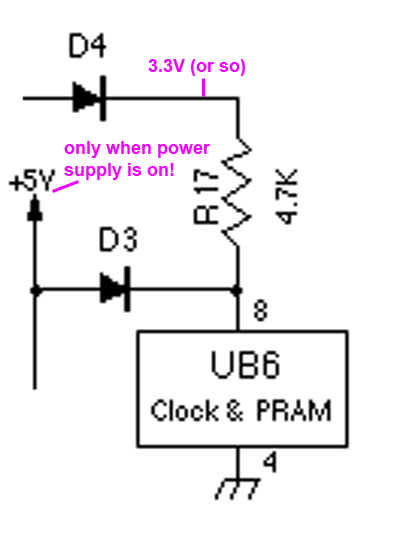
This portion of the circuit is responsible for powering the clock and PRAM. On most (all?) of the Macs that came after the II/IIx, this is the *only* thing the single 3.6V battery is used for, at least as far as I know.
Recall that I already explained that there is about 3.3V on the cathode of D4 coming from battery B2. The 4.7KΩ resistor R17 is limiting the amount of current that will be supplied to UB6, the clock/PRAM chip. So…when the computer is turned off, the battery B2 is powering UB6. D3 is preventing the battery voltage from going into the +5V rail (which will be 0V when the power supply is turned off).
When the power supply turns on, the +5V rail actually has 5V on it. D3 will allow the 5V to go through into UB6, so the +5V rail will power UB6. I believe the 4.7KΩ resistor (R17) makes it so that the 5V rail does most of the work powering UB6 instead of the battery when the power is on. D4 is also (I believe) preventing the circuit from sending +5V into the battery circuit when the computer is powered on.
This part of the circuit is pretty simple! I don’t think a problem in here would necessarily prevent the computer from turning on, but it might prevent settings from being remembered while the power is off.
Power On
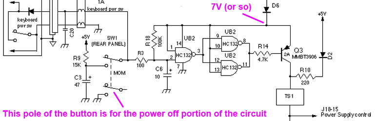
OK, here is where things really get interesting and more complicated. This is also where it will become obvious that both batteries must be installed in order for the II/IIx to boot. Recall that the cathode of D6 has about 7V on it or so. It powers UB2 (which is a 74HC132 containing four NAND gates–three are used, one is unused). UB2 doesn’t draw much current, so that’s why the diodes mentioned in the battery portion of the circuit don’t have much of a voltage drop. Without the batteries, these NAND gates will not be powered at all, and therefore the power circuit won’t work. It’s a good thing UB2 doesn’t draw much current, because otherwise the batteries would run out of juice too quickly.
Supplying 7V to the 74HC132 is a bit risky — it’s within the allowed range, but the datasheet I have recommends a maximum of 6V. Whatever–it seems to work. [Edit: The discussion about 3V vs. 3.6V above probably explains this discrepancy]
The 7V rail also goes to the emitter of transistor Q3, which is a PNP transistor. We’ll see in a minute, but when the power button is not being pressed, the transistor is turned off, so it shouldn’t be drawing any current.
Additionally, the 7V rail is directly connected to one of the inputs on each of the three NAND gates. In effect, it means each one of these NAND gates is really acting as an inverter (e.g. a logic 0 at the other input becomes a logic 1 at the output, and a logic 1 becomes a logic 0). This is because:
- 1 NAND 1 = 0
- 0 NAND 1 = 1
I’ll go into this in a bit more detail when I describe what happens when you press the power button.
Finally, the 7V rail goes through the 100KΩ resistor R18 to the second input of the leftmost NAND gate. This is a pull-up resistor that keeps the second input of the NAND gate pulled up to a logic 1 by default. The 100Ω resistor R3 is also connected to this part of the circuit, but the other end of it is floating when both power buttons are not being pressed, so it doesn’t really affect the circuit until a power button gets pressed.
So in the default state when the system is plugged in but no power button has been pressed:
- The leftmost HC132 NAND gate has both inputs at 7V. This means its output will be 0V.
- The output of that first NAND gate is fed into the other two NAND gates.
- Each of those NAND gates has one input at 0V, and one input directly wired to 7V, so they are both outputting 7V.
- Since 7V is going into the left side of R14, there is no current between the emitter and base of the transistor. The transistor is turned off.
- Because the transistor is turned off, the power supply control pin (J18, pin 15) is left floating (remember, the +5V output is not supplying 5V yet, since the power supply is off).
- Thus, the power supply stays off.
When the keyboard power button is pressed, the left side of R3 is grounded. This pulls pin 2 of the HC132 NAND gate to ground through the 100Ω resistor R3. So:
- The leftmost HC132 NAND gate has one input at 0V, and one input directly wired to 7V.
- The output of that NAND gate is thus 7V, which is fed into the other two NAND gates.
- Each of these NAND gates has 7V going into both input pins, so they are both outputting 0V.
- Since 0V is going into the left side of R14, current is flowing from the emitter of the transistor to the base of the transistor. The transistor is turned on and allowing current to flow from the emitter to the collector.
- Because the transistor is turned on, the power supply control pin is driven to 7V or so (just assume that TS1 is a short circuit for now–it will be described in more detail in the power off circuit description)
- Thus, the power supply turns itself on.
As soon as the power supply turns itself on, it begins outputting 5V. 5V goes through D2 and R10, pulling the power supply control pin up to +5V (minus the diode drop) through the 220Ω resistor. As soon as you release the power button, this mechanism keeps the power supply control pin high. Otherwise, the power supply would immediately turn itself back off.
The rear power switch does essentially the same thing as the keyboard power switch. When you press it:
- It completes a circuit to allow the battery to begin charging up capacitor C3, which is discharged when this process begins.
- The left side of R3 starts at 0V and slowly starts raising up as C3 charges.
- Since C3 starts at 0V, the same steps are followed as when the keyboard power button was pressed, and the power supply turns on.
- After the power supply turns on, 5V is available through R9, so C3 will charge up to 5V.
- C3 charging up to 5V is an important detail. If the button is later used for turning the computer off, the rear power switch won’t try to turn on Q3 at the same time it tries to turn the power supply off. It also gives you some time to release the power button before the system tries to turn itself back on again.
Wow! I may try to add some more diagrams in the future to depict it a bit more clearly. It’s a lot to digest.
You may be wondering: what is the point of the three NAND gates? At first glance, all they are effectively doing is repeating the input value that came out of R3. The purpose seems to be to allow better current drive capability for controlling the transistor, and a clean output that ensures that the signal controlling Q3 is either on or off, and not somewhere in between as capacitors charge up.
The three NAND gates essentially combine to create a buffer with double the current drive capability of a single NAND gate’s output. As long as all of the NAND gate pins are connected together and the NAND gates are working, you can assume that a low value at pin 2 of UB2 will turn the transistor on, and a high value at pin 2 will turn the transistor off.
Power Off
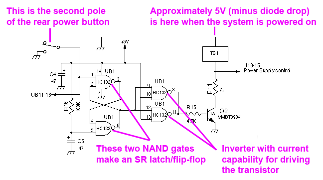
Just like the power on part of the circuit, the power off part of the circuit uses NAND gates that make it look way more complicated than it really is. These NAND gates are powered by the power supply’s +5V line. The two leftmost NAND gates form an SR latch. The SR latch’s top “set” input is connected to UB11, pin 13 (and the power button’s second pole). I believe this line is pulled up to +5V by a pull-up resistor inside the 6522 VIA (UB11), keeping it high (deasserted) while the computer is running. UB11 pin 13 is the /POWEROFF signal. At startup, C5 is fully discharged to 0 volts, so the SR latch’s “reset” input is low (asserted), which sets the SR latch’s stored “Q” value to 0. Then, C5 charges up, so the “reset” input goes high (deasserts itself) and stays deasserted while the computer is powered on. So the entire time the computer is running, the SR latch’s “Q” value is 0.
The !Q output of the SR latch is connected to the next two NAND gates, which act as an inverter just like in the power on circuit as I described earlier. So the output of the dual-NAND-gate inverter connected to R15 is really just the noninverted Q output of the SR latch, but with twice the maximum current. Thus, the voltage on the left side of R15 is 0V while the computer is on, keeping the NPN transistor Q2 turned off. Remember that the power supply control pin (J18, pin 15) is being pulled up to +5V in the power on circuit, keeping the power supply turned on.
Let me explain TS1 now. TS1 is a temperature switch. During normal operation, it acts like a short circuit. If the temperature gets too hot, it becomes an open circuit. If it becomes an open circuit, the power supply control pin is no longer pulled up to +5V, so the power supply shuts off (I’m pretty sure the power supply has a weak internal pulldown on that pin). During normal operation, TS1 will act like a wire.
When you tell the computer to shut down, the computer drives UB11 pin 13 (/POWEROFF) low. This causes the SR latch’s “set” input to go low, so it’s now asserted. This makes the !Q output low, which makes the inverter output high, so Q2 turns on, connecting R11 to ground. Now there is a 27Ω pulldown pulling the power supply control pin low, and a 220Ω pullup pulling the power supply control pin high (in the “power on” portion of the circuit). This is a voltage divider, so the voltage at the power supply control pin will be approximately 0.5V. This is low enough to tell the power supply to turn off.
If you press the power button on the back of the computer, the same thing happens — it connects the SR latch’s top “set” input to ground, and the exact same thing happens.
Troubleshooting
OK, so I have tried my best to explain what’s going on in each portion of the circuit. If you have a broken power circuit, how do you fix it?
The system will not power on
First of all, there are a few traces that have a tendency to go bad because they run nearby leaky capacitors:
- Make sure that the rear power button, R3, and the pin of L2 that goes to the keyboard power button are all connected together. (Note that R3 is on the bottom of the board)
- Make sure that R3, R18, C6, and pin 2 of UB2 are all connected together.
Of course, make sure you have removed, cleaned around, and replaced all of the electrolytic capacitors on the logic board.
Make sure that all of the connections between R3, UB2, R14, and Q3 are OK. If you can, use a voltmeter to verify that the NAND gates are operating as expected when you press either of the power buttons. You can do this with the logic board out of the computer as long as the batteries are installed.
Check the power supply control pin (J18, pin 15) to see if it’s correctly getting a voltage when you press either of the power buttons. If it is, there’s a chance that the power supply is at fault.
UB2 is somewhat near a capacitor. There’s a good chance that some of its pins have lost connectivity due to corrosion. Check every pin on UB2 and make sure it has connectivity as shown in the schematic.
The keyboard power button works, but the rear power button doesn’t
There are only a few parts of the circuit that could cause this. Make sure R9, C3, the rear power button, R3, and the keyboard power button pin of L2 are all connected as shown in the schematic diagram. For the rear power button to not work when the keyboard does, one of the connections between those components has to be broken.
The system powers on, but it won’t power off
UB1 is extremely close to a capacitor. There’s an extremely good chance that it has lost some connectivity due to corrosion. Verify all connections.
See if the output of UB1 pin 8/11 is correctly going high when you press the rear power button while the system is on. If not, follow the circuit and see where the broken trace is.
Final thoughts
I thought this would be a good idea to explain the circuit in more detail. This has turned into quite a long-winded explanation, and it doesn’t have quite as many pictures as I would have hoped. Maybe this would be better as a video or an animation that shows what the circuit is doing. For now, I hope this is enough to help someone out there troubleshoot their Macintosh II/IIx power circuit.
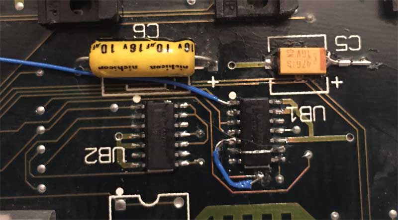
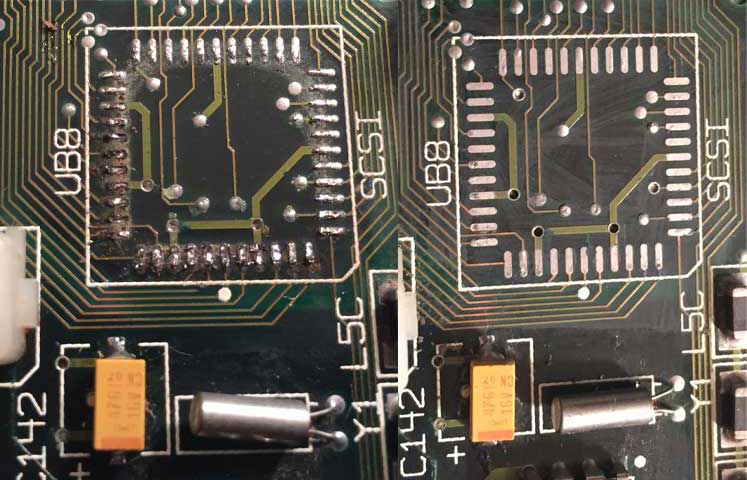
In my particular case, a trace was broken in the R3-R18-C6-UB2 group of pins that should be connected together, and UB1 was completely covered in capacitor leakage, which had very badly corroded its pins and solder pads. I ended up replacing both UB1 and UB2 to be safe. A trace between a via and C5’s positive end was also broken and needed a patch wire. I had to run several patch wires to repair broken traces:
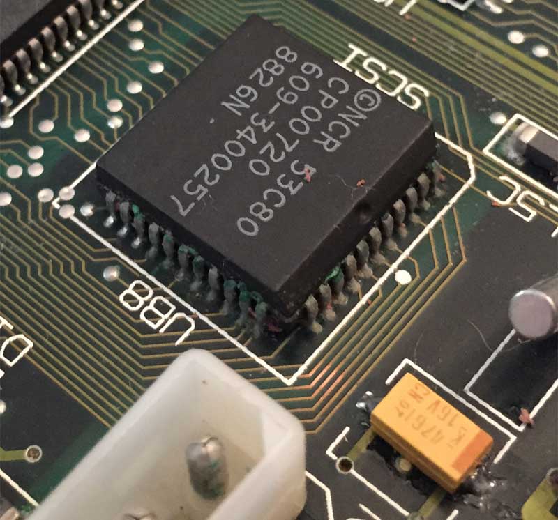
By the way, this wasn’t the only problem with my IIx. This was actually the last part of the logic board that I fixed. The whole power on circuit can be bypassed by tapping a 3.6V battery between ground and the power supply control pin, so I did that for testing until I repaired this circuit. The power supply would turn on, but nothing would happen. It turns out that there were a ton of other traces that were corroded. The 53C80 SCSI chip (again, near a capacitor) was very badly corroded, so I removed it, cleaned the solder pads, and replaced it with a new one. One of the solder pads had a break from its trace, so I had to run a patch wire. I also found several other broken traces on solder pads near two chips on the board.
It’s been a wild ride, but I now have a working IIx!


This is a great explanation of a common failure area on Mac II series logic boards. Thanks for putting all it all together!
Thanks Steve! I really enjoyed tracing out the circuit and writing this up because it finally helped me sort of understand how BJTs work.
Yeah i really enjoyed reading this.
Thanks for taking the time to write up such a great post.!
Charles
Not sure I will ask this correctly but how do you know which pins on UB2 are which? Not sure how they are numbered compared to the drawing. I can jump start my IIx and power it off from back after started and it stays on but will not power back on from switches. So switches dont work on power on and I need a little insight on how the traces are numbered to see what to fix I guess.
Hey Jason,
Pin 1 is in the upper left (top side of chip is marked with a dimple), and then they count down the left side and up the right side of the chip. Best explained with a picture:
Great article Mr. Brown! I have 2x Mac II that has this problem and was looking for schematics and this exact information.
Thank you very much for your time writing this.
Patrick.
Hello,
Do you know of a schematic of the power on/off circuit for the Mac LC/TV?
Thank you.
Hey Patrick,
Thanks for your kind words! Here are the schematics I know of:
http://www.maccaps.com/MacCaps/Schematics.html
The Mac TV’s startup circuit should be pretty similar to the Color Classic. I fixed my Color Classic by verifying all the vias/traces near the CUDA chip, no schematic necessary. I just removed the CUDA chip, took a picture of both sides of the board, matched up the vias, and made sure the connections were actually there with my multimeter. Found one bad via, patched it, re-soldered the CUDA chip, and it started working again.
Hello!
Great idea about the CUDA chip. I removed the CUDA chip and all surroundings components, checked all traces, vias, pads, etc… (I already recapped this board, btw)
The only thing I found is one broken via that goes to one pin of the little red button (the CUDA switch?). Now this via goes to a resistor and finally goes to a pin of the CUDA chip. The other pin of the switch is going to GND and this via is fine.
Could this prevent from powering on?
Thank you.
Patrick.
Hey Patrick,
Yep, that is the CUDA switch. You just reminded me of something. Check out this thread, where a guy I know was able to get his Mac TV booting by removing the CUDA switch — even though it didn’t appear as a short, it was doing something weird and keeping the CUDA in reset. Definitely would be worth playing around with that part of the circuit!
https://www.thinkclassic.org/viewtopic.php?id=691
In my opinion, a broken switch trace probably shouldn’t be preventing power on…but what bbraun saw on his Macintosh TV makes me believe you should definitely play around with the CUDA switch portion of the circuit.
Ok, I did look at the switch, removed it and it didn’t help.
At this point, I’m thinking that it might be the CUDA chip itself. the PCB is fine.
On the CUDA chip, there is sticker with a version number written on it. That sticker seemed yellow originally, but half of it is brownish, like burnt.
I’m wondering if the chip might have got very hot at some point and just broke.
I’ll continue hunting!
Patrick.
Success! I finally found the issue. The culprit was capacitor C201. I didn’t notice at first but it was discolored a bit. I tested it with an ESR meter and it was bad. Replaced it and boom the MAC TV boots!
Thanks very much for your help!
i am running out of cuda chips, have been getting some lately that have a leg rotted off usually its pin 13 or others. what pin would i have to jump in-order to do like a force power on.? atleast the CC and the 5x have a power on and off switch in the back.
Thank you Doug!
I finally got my II powering on correctly. It ended up being (what seems like a common issue) of the trace from R3 to the left side of the board being corroded away. I ran a wire between two neighboring vias and success!!
-Mike
Greetings – I love your article and work. I have Macintosh II, with 40M Quantum, 800KB and SuperDrive, and I think the memory capacity maxed out (I haven’t used in almost 30 years). I replaced the two 3.6V PRAM batteries. One was swollen but no leaks. This computer has the piggyback board to hold the two batteries, plus the 1000uf cap. I was purchased a monitor that arrived today. I powered it on from the keyboard momentary switch …. ah, the memories flooded back – but no chime, black screen, Drive was spinning and heard a little seeking going on. But not blinking ?-mark.
I don’t know what OS the command+option+P+R came to be, but I tried that hoping the PRAM might be restored. No joy. I powered it off from the back switch.
I waited a few hours, tried again, and the power on doesn’t latch. I tried the keyboard and rear switches, and it has power briefly (a couple of seconds), then powers off. I’ve looked the motherboard over top side only, and see no sign of leaking caps.
Any thoughts?
What is SW1 and SW2 – the momentary switches on the right side of the computer (as you face it)? As I recall, one is a reset switch but I have no idea.
Thanks in advance !
Hi David,
Command+Option+P+R resets the PRAM, but if you’ve changed the batteries the PRAM will already be reset — so you shouldn’t have to worry about that.
It’s a little concerning that you didn’t get a chime and the screen stayed black the first time. Are you 100% sure there’s no leaky capacitor damage? Pretty much every system I’ve seen that is this old has leaky caps.
That’s really strange that the system powers itself off. It’s definitely still possible that the power circuit is failing to keep everything powered properly. It could also be that something is causing the temperature switch to trip, or the power supply is having an issue. I still lean toward leaky caps having damaged something in the circuit being the most likely scenario. Have you changed the capacitors yet? It’s possible they have lost some of their “oomph”. Some of the caps are involved in the power circuit.
I don’t know which one is which, but one of the two side switches is a reset switch, and the other one is the programmer’s switch, which drops you into the debugger when you press it.
Just wanted to chip in with a big THANK YOU for this super valuable resource!
I recently acquired a Mac II which had a number of issues. The PSU was completely dead, but luckily this turned out to be the rectifier… once I sourced a replacement, it was back up and running. The II on the other hand, could only be fired up using a ‘jump start’ and would only stay running with external power applied to the Power Supply Control pin. There were plenty of signs of leaky caps… so I began with a full re-cap. This only made things slightly better… there was still no sound and it still needed to be jump-started. The ‘better’ part was that once started, it would stay running, and, it would power-off with a “Shutdown” or by using the switch on the rear.
I’d put it on the back-burner while I worked through other projects, but pulled it out last weekend to have another go.
The sound issue turned out to be a dead speaker… go figure. Once I put the one from my other Mac (a IIx) in, the chime was back. The power issue was more if a challenge… Thanks to your awesome write-up I was able to make my way through the circuit. I cleaned up the two Nand gate TTL chips [UB1 & 2] – which both had corroded pins thanks to one of the caps spilling its guts… still no joy… I then followed the advice to check the connection between R3 and R18 (which meant pulling the board out again) and discovered there was none. A close inspection revealed that the two were connected via a trace that went almost the entire width of the board – on the top side! I noticed when following this trace that it passed by several caps that had also spilled their guts. I grabbed some wire-wrap wire and ran a jumper between the two points under the board… and… Viola!! My II now powers on from the keyboard or rear switch – with no need of a jump-start!
Thanks once again for putting the time in to document this and save another Mac from the graveyard!
-Lee
Just to add… although my IIx was able to contribute a speaker to resolve the no-sound issue on my II… it too was suffering from power-on/off issues – needing a jump-start. After re-capping, everything was working *except* power-on (just like my II). I can confirm the Doug’s comment above about component numbering – “The IIx *IS* slightly different”. I presume mine is a later ‘different’ one. For the power-on circuit… pin 2 of UB2 *is* still connected back to the Power and ADB logic, and R3 is still nearby those… but the components connected to UB2 are R19 and C8.
Hope this helps someone… thanks again for the excellent resource! My IIx no longer needs jump-starting!
BTW… as an aside, both my II and IIx came with original batteries… these were 3V *not* 3.6V… I’ve replaced them with sockets and also 3V 1/2 AAs… Both Macs seem happy.
-Lee
Just to concur with Doug’s reply above… @David, I recommend you re-cap your ‘board. I’ve re-capped about a dozen ’80s/90s Macs over the last couple of months, including my 2 x IIs… The latter both required jump-starting and my IIx powered-off if 5V was not maintained on the right-most (from the front) pin of the PSU connector (I believe J18-15?). Here’s one how-to video for jump-starting – https://www.youtube.com/watch?v=6Mvn5z6AJK4.
FYI, I used one of those USB battery-banks ($5 at Walmart) and a stripped USB ‘power’ cable to wire in my jump-starter.
Re-capping will probably also cure your no-sound issue, since there is at least one ancient (probably expired) electrolytic near the sound chip… Good luck!
-Lee
Just realized I missed Mike’s comment up above, glad you got yours working Mike!
Thanks for all of the info you provided, Lee! I didn’t realize that the original batteries were just 3V. I think the original batteries being 3V explains something for me. In the post, I wrote:
“Supplying 7V to the 74HC132 is a bit risky — it’s within the allowed range, but the datasheet I have recommends a maximum of 6V. Whatever–it seems to work.”
Sounds like the original batteries would have been perfectly within spec on that. That makes a lot more sense!
Doug > I didn’t realize that the original batteries were just 3V
You’re not alone… I’ve seen other ppl mentioning 3.6V – which is standard on most any new Mac (with a single battery). I did originally see your comment about 7V… but couldn’t spot it when I posted… It does sound like 2 x 3V = 6V – which is then dropped by the diodes – is more within spec.
Doug> Thanks for all of the info you provided, Lee!
Absolutely my pleasure… were it not for this resource you’ve created… I’d be stuck with 2 x ‘dead’ Macs!…
-Lee
Yup, I did googling and you are most definitely correct. I will update my post with the newer voltage info! I don’t want to be the reason for someone to fry their NAND gates, haha.
The 74HC132 is rated as an absolute max of 7V, and recommended max of 6V, at least according to the datasheet I was looking at. So running it at 7V is right at the edge of what is allowed, seems kinda risky. But I bet a lot of people do it. Either way, I want my post to contain 100% info 🙂
Hi,
Thanks for the article. I little over my head, but I am trying to learn. I have a pristine (to the naked eye) IIfx. Brand new batteries on the motherboard. When I tried to power on at the back of the case, I get a very fast green light from the power supply and then nothing. When I press power on the keyboard, same thing. However, if I keep the power button on the keyboard pressed, the machine boots just fine. When I remove my finger from the power button, the machine loses power instantly.
Any thoughts on what might be causing this odd behavior?
Thanks
Hey Brad,
The IIfx power circuit is pretty similar to the IIx’s. Gamba also created a schematic for the IIfx power circuit:
https://web.archive.org/web/20160801212601/http://home.earthlink.net/~gamba2/images/macIIfxsch.GIF
Based on the schematic, I’d check around UJ18 and UI18 for any corrosion or damage. I’d also recommend making sure you have replaced any metal can capacitors and cleaned where they might have leaked. I think the IIfx has a few of them.
Thanks Doug!
This article was very helpful. I had corroded traces around the Nand Gates UB1 and UB2. I repaired them and was able to start up. My issue after this was I wasn’t able to shut it down. UB1 was clean. I found trace damage way across the board near C9, repaired that and now I have a working Mac IIx that starts up and shuts down. Thanks so much for explaining this.
Awesome Steve! Nice job, glad this post was helpful!
I have two Mac IIfx that were damaged by the two vomiting Maxell batteries. I’m still trying to repair them. I think I have all the connections, however I can only boot by jump starting them and immediately get the death chime. Weird that both have the same issue. They will not POST. So it’s either bad RAM or a SCSI issue.
Anyway, I bought a Mac IIx motherboard to maybe stick in one of the Mac IIfx cases for the time being. I found an interesting issue. The Mac IIfx power supply will not boot the IIx board. My Mac IIx power supply is 699-0389 (1988) and the Mac IIfx is a 699-0393 (1990). I do get 5v at pin 15, but nothing else including no -12v at pin 14.
I still have issues with the new Mac IIx board. I stuck it in my working Mac IIx case, it immediately booted when I plugged it in without touching the power buttons. Pressing the power button does not turn it off. I’m certain I will find the broken traces. I do have connections with R3, R18, C6, and pin 2 of UB2.
When it is powered on at UB1 pin 8 and pin 11, I get 5.1v. On my other Mac IIx I have 0v on those pins and I get a proper shutdown.
Odd thing with this board is I get no video no matter which nubus slot I use. I did an initial voltage check on the slots and I have voltage. I have a Flir infared camera and will check if I get any activity. I’m guessing a IC that controls the nubus slots(?).
Thanks again for the great write up. I find it very helpful.
Update:
I was able to get startup and shutdown. I had a larger than normal solder blob on the back of the board on C8 that was touching a test pad nearby. Your guide once again was helpful.
I tried my Mac IIfx board in the Mac IIx case and the power supply will not power up the fx board. So power supplies are not interchangeable.
My issue now with the new Mac IIx board is no video. I have tried known working video cards and have power to the nubus slots. All voltages are reading 11.94v at pin 32.
I took some photos with my Flir camera and the board shows activity. Power is present, so I am guessing there is a capacitor or resistor that has failed that drives the nubus slots.
Again, thanks for your guidance. I will be studying the bomarc schematics.
Hi,
thanks for this extremly helpful explanation of the circuitry. I have a Mac II which has two issues, eventually you can give me a hint on what could be the issue:
1. The system does not power on either by rear or keyboard switch, but it does automatically when i remove/insert the two batteries.
2. The batteries are both drained to 0.2 V at insane rates, takes about 24 hours (no power cable connected to psu)
Any clues?
Hi Egon,
Sounds like something in the startup circuit is drawing too much current from the batteries and draining them. A few things that come to mind: Maybe check to see if Q3 is stuck on? When Q3 is on, it draws current from the battery. Also, check for short circuits around the UB2 chip? The batteries are directly powering UB2, and the battery power is also passed through Q3 when it’s on. Other than that, the only real connection to the batteries from the startup circuit is R18.