Last year, I repaired an NZXT Signal 4K30 USB capture device that I bought on eBay for cheap. It was completely dead, and the cause turned out to be a bad solder joint on an inductor, which prevented power from getting to a crucial part of the board.
After I fixed it, I tried using it to capture signals from a bunch of different HDMI source devices to make sure it worked correctly. As I said in my last post about it:
I did find one 720p60 HDMI source that it doesn’t like — the captured video shows up as pink and green.
In that post, I also pointed to a few Reddit threads (1, 2) where similar issues had been observed on a PS5 and Nintendo Switch, respectively.
Here’s a snapshot of what captured video looked like from the one HDMI source that it didn’t like:

You can see that the colors are green and purple. They’re completely wrong. I knew from past experience with video encoders and decoders that this is very typical behavior if you have a mismatch between RGB and YUV video. I doubted it was faulty hardware, especially since other people on Reddit had seen the exact same symptom.
I left it at that. I didn’t care that this one device wouldn’t capture correctly, and I didn’t bother contacting NZXT about it. I’ve noticed that since then, the device seems to have completely disappeared from the market. You can’t buy it on Amazon or Newegg anymore, and NZXT’s website doesn’t mention it anywhere except under support. It’s pretty clear that NZXT exited the capture card market. If I contacted them now, I’d be shocked if they could do anything about it.
Last night, a thought randomly jumped into my mind. I’ve been using Claude to do some pretty in-depth reverse engineering and bug investigations lately. For example, here’s a reverse-engineered Linux kernel V4L2 driver for the Elgato Game Capture HD60 S that I investigated in depth a couple of years ago. What if I had it look into this problem? It would be a nice way to completely finish off the first post where I repaired the hardware problem. Together, could we fix the final issue, which I assumed was a firmware problem?
During the hardware repair, I had already documented all of the different components used in the device, so I gave that all to Claude, along with a description of the problem, pictures of the issue from the Reddit posts, NZXT’s last firmware update for the device released in 2022, and a checkout of a GitHub repository containing ITE’s driver for the IT6805 HDMI receiver IC used by the Signal 4K30. I also pointed out that I suspected it was some kind of RGB vs. YUV mismatch because I’ve seen this happen in the past when developing firmware for video devices.
15 minutes or so later, Claude got back to me with results. It agreed that it was a YUV vs. RGB mismatch issue. It pointed out what it thought were a few bugs in the firmware that looked promising. To be sure, it asked me to verify a few things about the detected signal. It told me that the Cortex-M0 microcontroller has a UART with debug output. I found the unmarked debug header on the PCB, figured out which pin was the TX pin (and the baud rate) with my portable oscilloscope, captured its output with the problematic HDMI source device attached, and pasted it back. I also used my reverse-engineered Game Capture HD60 S Linux driver listed above to provide more details about what type of signal the problematic source was outputting.
The source device was outputting in DVI mode instead of HDMI mode. This was a major clue. DVI mode means it doesn’t have some of the extra packets that are included with newer HDMI sources, such as AVI InfoFrames.
Claude pinpointed a section of code in ITE’s stock IT6805 driver that looked wrong, and confirmed this code was also present in NZXT’s firmware. Here’s a trimmed-down snippet:
// REG6B[5:4]: Reg_ColMod_Set Input color mode set 00: RGB mode - 01: YUV422 mode, 10: YUV444 mode, 11: YUV420 mode
chgbank(0);
if (iTE6805_Check_HDMI_OR_DVI_Mode(iTE6805_DATA.CurrentPort) == MODE_HDMI)
{
    HDMIRX_DEBUG_PRINT(("---- CSC HDMI mode ----\n"));
    ...
    hdmirxset(0x6B, 0x30, iTE6805_DATA.AVIInfoFrame_Input_ColorFormat << 4);// seting input format by info frame ??? do not need ???
    ...
}
else
{
    ...
    HDMIRX_DEBUG_PRINT(("---- CSC DVI mode ----\n"));
    hdmirxset(0x6B, 0x30, 0x10);                        // seting input format to RGB
    ...
}
This code is figuring out whether the IT6805 has detected an HDMI or DVI signal, and configuring various registers based on that result. One such register tells the IT6805 how to decode the incoming video signal. If it’s an HDMI signal, it grabs the color mode directly from the AVI InfoFrame and puts it into bits 4 and 5 of register 0x6B.
On the other hand, if it’s a DVI signal, it knows that the video signal has to be RGB, so it tries to configure those same bits in register 0x6B for RGB mode.
Except…the code is wrong. The comment correctly says it should be configured for RGB in this case (“seting input format to RGB”) but what it actually does is write 01 to bits 5:4, which means YUV 4:2:2 mode according to the comment at the top.
I can’t speak for certain, but I think I see the mistake the original ITE developer made. When my eyes first jump to the comment for RGB mode, what sticks out in my mind is “RGB mode – 01”. But that’s my brain parsing the comment incorrectly. What it really says is “00: RGB mode”. I think the fact that the comment only uses that one hyphen and then uses commas for everything else throws me off. I wouldn’t be surprised if the original developer made the same kind of parsing error in their brain.
Okay, so I now had a theory. How could I test it? The debug UART unfortunately didn’t provide a way to read or write the IT6805’s registers, or I could have easily tested it out.
In exchange for a fun story and the potential to be able to release this fix for everyone, I was willing to risk bricking my device. Claude was very hesitant about this and wanted me to try accessing the MCU through SWD to back up its firmware first, but I decided to just full send it. I’ll bet the chip was locked anyway. I had Claude reverse engineer the NZXT firmware updater utility to figure out how it works, and also figure out if it would be safe to simply patch the firmware to change it to write 00 rather than 01 to those bits in register 0x6B. I was particularly worried about changing a checksum or CRC in the firmware image, but Claude was pretty sure the MCU firmware was not checksummed in any way. It fixed the bug in ITE’s driver by patching a single byte in the NZXT firmware to change a movs r2, #16 instruction to movs r2, #0.
Claude also gave me back a command-line utility that reflashes the firmware using the DLL included with NZXT’s updater. I couldn’t just use NZXT’s stock utility because it refuses to install a firmware update file if it thinks the device is already up to date.
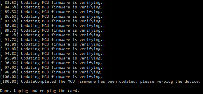
Despite the potential that I could render my capture card completely inoperable, I decided to run the updater. It went through the whole update process, which ended looking like this:
I power cycled the capture card as the instructions told me to, and then opened up OBS to see if the behavior changed at all.
To my relief, it all still worked after the update, and even better, the bug was gone! The colors looked perfect when capturing my DVI source device.

That was definitely the bug. It’s actually a bug in ITE’s driver, so it probably affects lots of devices that just drop in this vendor code without actually testing it against a bunch of different HDMI sources and sinks.
In my case, the source device I’m using doesn’t provide InfoFrames at all, so an HDMI sink device encountering a signal without InfoFrames is supposed to assume the data is RGB. As for other people’s situations, they could hit this same problem even with a modern HDMI source device if they have an old DVI monitor attached to the passthrough port whose EDID doesn’t support HDMI mode for whatever reason.
It’s very possible that the PS5 and Switch in the Reddit posts were encountering a completely different problem that happened to have the same symptom. All I know is Claude’s bug fix actually worked for me, and now I can use this capture card to capture this particular sink device with perfect, vibrant colors!
In case it is useful for someone else in the future with the same discontinued NZXT Signal 4K30 capture card, I’m providing the firmware bug fix to the community. Here’s my GitHub repository for it, along with installation instructions: https://github.com/dougg3/nzxt-signal-4k30-color-bug-firmware-patch/
My mind is still pretty blown away by how good Claude has become at hunting for bugs and reverse engineering firmware. I didn’t run into any problems during this particular analysis, but I will say that sometimes I run into Claude’s cybersecurity guardrails when trying to track down issues. I understand why these safeguards are in place, but it can be frustrating at times. I’m not officially a cybersecurity professional, so I’m not sure if it would be worth even trying to apply to their Cyber Verification Program. But I think there are times when reverse engineering and even local hardware-in-hand exploits have legitimate non-nefarious purposes, like being able to replace a sketchy device’s buggy closed firmware with an alternative, improved open-source firmware. I wish there was a way as a hobbyist to communicate that intent to Anthropic without being hit with the guardrails!
Anyway, I didn’t run into that problem at all on this project. I would say that overall, this fix was a complete success! I tested it out with several HDMI source devices after patching the firmware, and now they all work great. It feels great to fully close the book on my Signal 4K30 repair story.
By the way, the sample picture I used for showing the color problem came from the Kodak Lossless True Color Image Suite. And yes, it was a direct capture from the 4K30 before and after the firmware fix!


no comments