If you’ve been reading my blog for a while, you might remember back in 2012 when I changed the startup sound on my Power Mac G3 (Blue and White). That was a fun introduction to the Forth programming language. I had to reverse-engineer just enough of Apple’s firmware update script to understand what was going on.
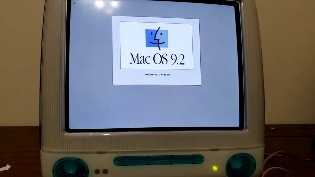
Recently, Aidan Halpin, a reader of this site, asked me if I could do the same kind of startup sound customization on his iMac. This particular iMac is officially known as the “iMac (Slot Loading)” and has a model identifier of PowerMac2,1. As you can guess from the name, it has a slot-loading CD-ROM drive unlike the original iMac that had a laptop-style tray-loading drive. By the way, Aidan’s iMac is special because it has a PowerPC G4 processor soldered onto the logic board instead of the original G3.
This is the next post in my series about upgrading my old Chumby 8’s kernel. Here are links to part 1 and part 2 if you missed them. As a quick summary, I got U-Boot working in part 1 and then got the SD card working in part 2. In this part I’ll describe the complicated process of how I got Wi-Fi working.
The Chumby 8/Insignia Infocast 8 has a built-in AzureWave AW-GH321 802.11g module. This is a pretty old module that doesn’t even support 802.11n, so it maxes out at 54 Mbps and the link is an archive.org link because it’s nowhere to be found these days. The module makes use of the Marvell 88W8686 chipset, which connects through the SDIO bus. SDIO is basically just the same as SD, except it’s for I/O devices like Wi-Fi and Bluetooth modules instead of SD cards. This wireless chipset is supported by a Linux driver called libertas.
This is a continuation of my previous post about upgrading the old 2.6.28 Linux kernel that came with my Chumby 8. In that post, I got a modern U-Boot working with SD card support, which is what I needed in order to boot Linux.
After I finished getting U-Boot working, I began work on the kernel. I based my work on the stable kernel version 5.15.33. I started by compiling a kernel using the bundled pxa168_defconfig file. I created a device tree file called pxa168-chumby8.dts based on pxa168-aspenite.dts. It needed a few tweaks. I specified the correct amount of RAM for the Chumby 8 (128 MB) and changed the model and compatible strings. I also disabled “twsi1” which is an I2C host. I wasn’t ready to deal with I2C yet. Here’s a small snippet of the relevant changed parts of my new device tree file.
As I mentioned in my last post, I spent a good chunk of my spare time over the past 6 months working on a project I’ve been thinking about for over a decade. I bought a Chumby 8 in 2011. It’s an 8″ touchscreen device powered by the Marvell PXA166 processor. It is essentially a souped-up digital picture frame with extra capabilities like speakers, a microphone, and Wi-Fi. There are a bunch of little Flash-based “apps” you can install for stuff like pictures, music, sports scores, weather, games, etc. I have no idea how many of the apps still work these days. Chumby actually went out of business a few months after I bought mine, although one of the founders stepped up to keep the service running. A variant of this device was also created for Insignia, which was called the Infocast 8″ Internet Media Display.
I was never really interested in using it for any of the stock functionality. I thought it would be a fun development platform. It would be exciting to make some custom apps in Qt or something. One thing that was a little frustrating was that it came with a Linux 2.6.28 “Erotic Pickled Herring” kernel circa Christmas 2008, which was ancient even at the time I bought it. This is a pretty common issue with Linux-based devices. I will even admit I’ve been responsible for some old kernels out in the field in Internet-connected devices. I don’t blame Chumby. It’s tough when the SoC vendor doesn’t submit their kernel modifications upstream or at least keep their fork up to date. I’ve been there.
I’ve been doing some Linux kernel development in my spare time over the past 6 months or so. The goal has been to get my old Chumby 8 (stock kernel 2.6.28) running on a modern kernel with custom firmware. It has been going really well and there have been lots of fun problems I’ve needed to solve along the way. I may write some posts about that process if there is any interest. It’s been a blast.
Anyway, I thought it would also be fun to jump into the current craze of OpenAI’s ChatGPT free research preview and apply it to Linux kernel development. Let’s see just how well this AI can write a basic kernel module that I describe. Can it improve the module as I ask it to make tweaks?
I started out by asking:
Write a Linux kernel module that prints “Hello world” to the console every 5 seconds. Also provide a Makefile for compiling it.
This post is going to be a bit different from my usual posts. It’s still about computers, but it’s about a different type of computer: the computer modules in my 2009 Dodge Ram 1500 pickup. Vehicles these days have lots of computers in them. I’ve historically been afraid to mess too much with them in fear of screwing them up. Something going wrong has much more serious consequences when it’s your vehicle, as opposed to a spare computer you’re dinking around with. I’m slowly getting more confident though.
I previously blogged about a strange problem I’ve been experiencing where my internet upload speed tests fail to reach the expected gigabit speed that my ISP provides — but only in Windows 10. I have a quick update on where I ended up with this problem, and a collection of further test results that point the finger at Windows 10’s TCP stack.
I didn’t mention this in my previous post, but the Seattle server I’ve been using for all of my testing (and seeing the problem with) is run by my ISP. The main thing I figured out, and I’m embarrassed I didn’t try this earlier, is that I do get my full upstream speed in Windows 10 on some (but not all) other nearby test servers, one of which is also run by my ISP.
I’m going to start this post off by saying that I feel incredibly spoiled to even be bringing up a problem like this given that I started out decades ago on a 33.6k dialup modem and today’s cable and DSL connections still have relatively low upstream bandwidth. But it’s still a technically interesting issue that I think is worth bringing up to a larger audience. The gist of what’s going on is: I’m lucky enough to live in an area where symmetrical gigabit fiber internet is available, affordable, and maintained by an awesome ISP. The problem is that although my downstream speed is fine, I’m not seeing my full upstream bandwidth during speed tests when I’m using Windows 10. I’m “only” getting around 300 to 400 megabits instead of the expected 940-ish I should see with a wired Ethernet test.
On a daily basis, I work on firmware for an embedded device that uses the BridgetekFT800. It’s a nifty chip that takes commands over SPI/I2C and turns them into an image displayed on an LCD. It’s very useful for displaying user interfaces with simple microcontrollers. Bridgetek is actually a spinoff company from FTDI, and this kind of solution seems right up their alley — take something complicated like USB or a display controller, and create a simpler interface for dealing with it, such as UART/SPI/I2C.
One thing that’s usually important about user interfaces is the ability to display text. The FT800 has a very basic capability for handling fonts. It’s not really much more than the ability to deal with sets of 127 sprites that each comprise a “font”. As a developer, if you want to use fonts aside from the (very limited) stock ones that come bundled in the FT800’s ROM, you have to create bitmap images that you upload into the 256 KB of available display RAM.
Several years ago, we had to deal with converting the user interface to display in a bunch of different languages, including Chinese. Most of the new languages we added weren’t a big problem, because we could just create a couple of fonts containing all of the special accented characters we needed and be done with it. Chinese, though, was a bigger challenge. There are so many different characters. Putting every character for every string into the limited display RAM is impossible. My coworker at the time came up with a clever script that automatically rasterized the font glyphs and created groups of different 127-character fonts for each displayed screen in the user interface. Every time you changed screens, the new set of fonts for that screen would be loaded into the display RAM.
A couple of weeks ago I found a really good deal on a Socket AM4 motherboard that supports the newest AMD Ryzen CPUs. The motherboard is an ASRock A520M/ac. It’s a very basic motherboard which doesn’t appear to be sold by any of the usual retailers anymore, but I couldn’t pass up on the deal, especially with the potential it had for being a fun learning project.
The reason I got such a good deal on it was because it was sold in non-working condition, but the seller and I both had a pretty good hunch about what was wrong. The seller said that they had bought it as an open box unit, but couldn’t get it to POST. However, they had only tried CPUs in it that were not compatible with the original BIOS version. I decided to have some fun and see if that was indeed the only problem. I didn’t have an older CPU available to easily test that theory. I did have a new Ryzen 7 5700G, which is only supported by BIOS revision P1.60 or newer.
Typically, there are several simple options for using a newer CPU with a motherboard that needs a BIOS update in order to support it:
Borrow an older CPU just long enough to install an updated BIOS. AMD has a program for handling this if you don’t have an easier way to borrow one. I don’t know if this is a valid option if I’m not the original buyer of the motherboard. AMD’s documentation requirements in order to participate seem pretty stringent based on the linked instructions.
Use the “USB BIOS Flashback” feature to update the motherboard’s BIOS even without a CPU installed. This particular motherboard doesn’t support that option.
Send it back to the retailer or manufacturer to update it for you. I have no idea which retailers/manufacturers might do this. There’s no way that Amazon, for example, would provide this service.
It’s possible that ASRock would have tried to help me out if I had asked, but I decided to turn this into a fun personal challenge instead: upgrade the BIOS on my own without using an older CPU.