TL;DR: The pinout of modern programmable Mac ROM SIMMs needs to be changed for correct operation in Quadras. If you’re interested in how I reached that conclusion, or at least want to see some cool pictures, read on below.
One thing that you usually discover when searching for info about these programmable ROM modules is that they’re compatible with the earliest 68030-based desktop Macs: the SE/30, IIx, IIcx, IIci, IIfx, and IIsi. The most common use of them is to set up a special custom bootable ROM disk using Rob Braun’s driver, Big Mess o’ Wires’ driver based on Rob’s, or Garrett’s Workshop’s driver. In general, the compatible ROM images out there are all using the IIsi ROM which is capable of booting any of the aforementioned Macs.
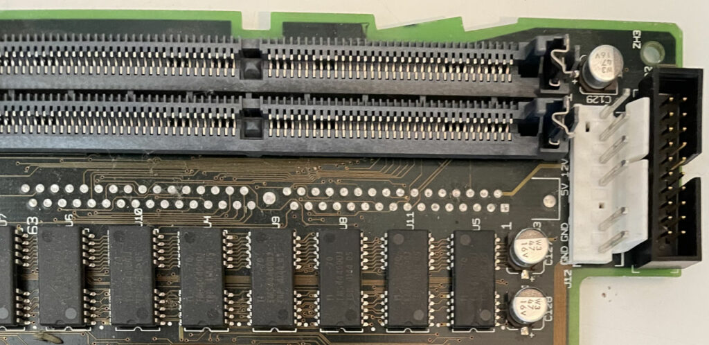
What you may not know is that most of the later 68k Macs also have provisions for a ROM SIMM socket, but aside from the very first Quadras (700/900/950) which always have the socket installed, it’s not usually populated. Some early production or prototype units have it, but most just have empty through-holes filled with solder where the socket would go.
Don’t worry, I already replaced those leaky capacitors before they had a chance to damage the board.
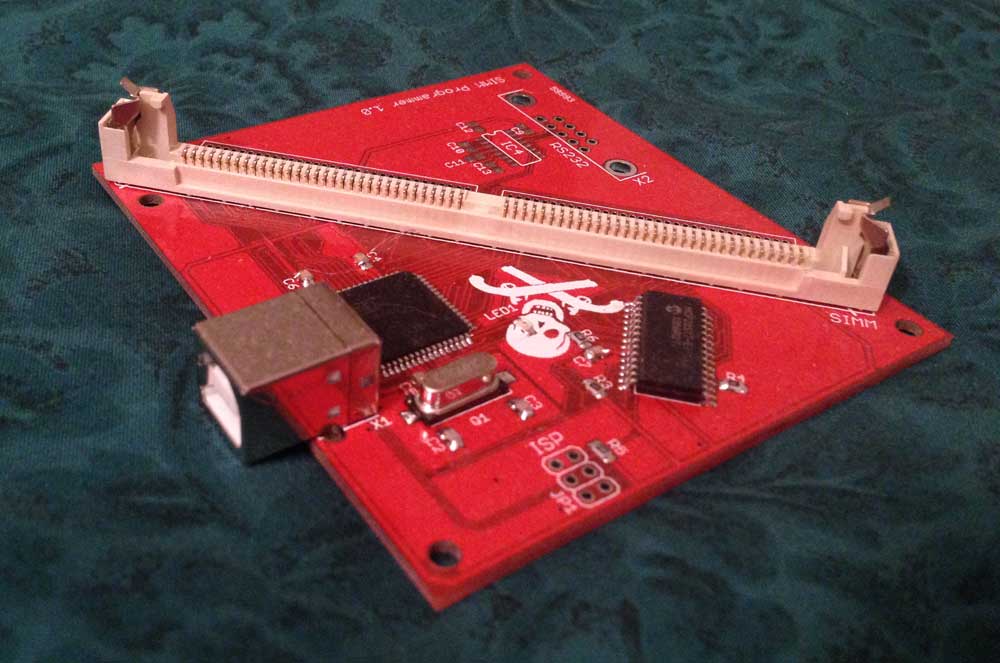
Several months ago, Will from CayMac Vintage reached out to me looking to resurrect my old Mac ROM SIMM programmer project. As a quick summary of that project, it provides a convenient way to program custom 64-pin ROM SIMM modules for vintage Macs from the late ’80s to early ’90s. There are several reasons you might want to do this, including: replacing an original ROM module that has gone bad, disabling the startup RAM test to decrease boot time in systems with a lot of RAM, bbraun’s amazing bootable ROM disk hack, or my startup chime hack. JDW recently made a cool YouTube video explaining custom ROM SIMMs if you’re curious about them. He even included some footage from 2003 of me playing basketball!
I used to make programmer boards and programmable ROM SIMMs and sell them to hobbyists, but it burnt me out. In particular, assembling the boards and the logistics of shipping were not fun to deal with. Thankfully, in 2016, Steve from Big Mess o’ Wires stepped in to take over. He made his own customizations to the programmer and made some really neat improvements to the bootable ROM disk driver. He still sells the Mac ROM-inator II SIMM to this day, but he stopped selling the programmer board. In the meantime, many other players have entered the market with custom ROM SIMMs, but nobody has been making the programmer available to the community, likely due to my non-commercial license on the PCB design.
Will was looking to fill that void. I helped him get going, but we discovered that the AT90USB646 microcontroller that I originally used was hard to find due to the chip shortage. At the time, it was easier to find the AT90USB1286 instead, which is essentially just the exact same chip, but with 128 KB of flash instead of 64 KB of flash.
I recently ran into an interesting warning on newer versions of ARM GCC, including the latest (as of this writing) Arm GNU Toolchain 12.3.Rel1. In particular I’m dealing with arm-none-linux-gnueabihf-g++. Here’s a very simple example program that demonstrates the warning:
I recently released a big update for my Mac ROM SIMM Programmer software which is written using Qt for cross-platform compatibility. As part of the update I wanted to release the Mac build as a universal x86_64/arm64 binary so that M1/M2 Mac users would be able to run it natively. It doesn’t currently compile for Qt 6, although I think I can fix that in the future without too much effort. However, Qt 5.15.9 and later do support creating universal binaries out of the box, so I decided to figure out how to set it all up.
Even though I think I have pretty decent Google-fu, it was difficult to piece everything together to accomplish this goal. I’m hoping this post can serve as a reference for people in the future. These instructions are based on Qt 5.15.10 because that is the latest version of 5.x that is currently open source. I did this on an M2 Mac Mini running macOS 13.5.1 Ventura.
First of all, before anybody suggests it, you can’t use homebrew to install Qt for this because it doesn’t supply a universal build of Qt. If you’re going for an open-source build, you will need to build your own Qt instead. I’m assuming people with a commercial license can just get compiled binaries from Qt. So if you have access to that, you can probably skip the step of building Qt. Otherwise, follow along with me…
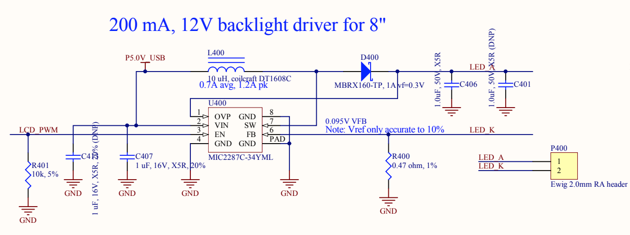
In the previous post in this series (here are links to parts 1, 2, 3, 4, and 5), I really got the Chumby to start looking like a Chumby. The display was alive! But getting the LCD controller working was really only one puzzle piece when it came to the display. The backlight needed more work so that I could control the brightness, and the touchscreen controller is a completely nonstandard design that is specific to the Chumby.
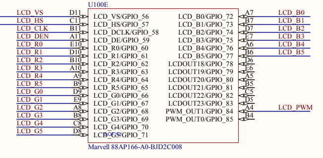
Let’s start with the backlight. This should be pretty straightforward, right? Looking at the schematics, the backlight control is connected to GPIO_84 (also known as PWM_OUT1) on ball A4 of the PXA166. I already knew that I could turn the backlight on full blast by using this pin as a normal GPIO pin and driving it high. That’s what I did in the previous post in order to quickly get it working.
A couple of months ago I stumbled upon a post on Hackaday about an inexpensive open-source USB 2.0 sniffer created by Alex Taradov. This is a really cool project! Normally, USB sniffers like this can cost thousands of dollars, especially if you’re paying for fancy protocol decoding and also want high-speed 480 Mbps support. This one costs about $50 in parts to assemble yourself, although it will take hours to solder and you will need some experience with hot air (or reflow oven) soldering since the USB PHY is a QFN chip with an exposed pad underneath.
I actually have an Ellisys USB Tracker 110b that I bought on eBay many years ago, but it only does low-/full-speed decoding. I thought this would be a good opportunity to upgrade my capabilities to also be able to handle high-speed USB sniffing, while also providing some good soldering practice.
Here’s my (very long) video about the process of building up one of these and programming it. I left in all the mistakes I made along the way. Why not show the world that it’s normal to make dumb mistakes when you build stuff?
I thought I’d use this post to explain in a little more detail what exactly a USB sniffer is. Why would I buy (or make) a hardware USB sniffer when Wireshark already has software USBPcap support in Windows?
At this point in my Chumby kernel upgrade project (parts 1, 2, 3, and 4 here), I had made a ton of progress but there wasn’t really much to show for it because I didn’t have the LCD working. Even though I had put a ton of work into the project, the display was still black. I knew it was time to get it working.
I started out with U-Boot. As a very basic overview of the LCD controller in the PXA168, basically you just set aside some of your RAM for a framebuffer, copy image data into it, tell the controller the format and address of the framebuffer, set up the clocking and timing, and turn it on. Then it just handles everything in the background for you.
The steps I listed above are overly simplified — there is more stuff going on with the PXA168’s display controller. But it’s enough to get a splash screen working in U-Boot. I booted into the old kernel and dumped the LCD registers using devmem. Here’s an example of this process. The LCD_SPU_DMA_CTRL0 register contains a bunch of format configuration bits for the framebuffer, such as which bits are red/green/blue. It’s at offset 0x190 in the LCD controller, and the LCD controller is located at an offset of 0xD420B000, so I could dump the 32-bit register value with this command:
devmem 0xD420B190 32
This resulted in a printout of the value of the register:
Update on 2023/05/19:ASUS has publicly acknowledged the issue and provided an explanation and workaround of their own (rebooting, or a hard reset if the reboot doesn’t fix it). The original post is below:
When I woke up today around 6:45 AM PDT, I didn’t seem to have internet service available. My phone told me that I was connected to my Wi-Fi network, but it didn’t have connectivity. “Hmm, that’s weird,” I thought. Maybe a fiber cut in the area or something? I looked at my IRC client on my desktop Windows PC, which is nice because it records timestamps of when I lose my connection:
My connection had been down for over 3 hours at this point. Weird! I figured I would log into my ASUS RT-AC86U router’s web interface and see what was going on. Something happened that I wasn’t expecting at all — the page wouldn’t fully load. Portions of it showed the little “sad page” icon indicating a connection error.
I tried to SSH into the router instead. The first few connection attempts failed, and then finally I got in. What I found, though, was that I couldn’t run any commands. It just spit this error back at me:
-sh: can't fork
OK, so something was really messed up. I decided to power cycle the router at this point. Maybe some weird glitch happened or something. Which would be odd — this router has been pretty rock solid since I’ve had it, aside from 2.4 GHz Wi-Fi issues over time. That’s another story I don’t want to get into today.
Anyway, when the router came back up everything seemed fine. But then, 40 minutes later, my connection dropped again with the same symptoms.
My cousin recently got ahold of me, saying that he was having trouble with his Brother FAX-2840 fax machine/laser printer. It still worked fine as a fax machine or copy machine, but he couldn’t print to it from his Windows 10 computer. He has a business where he needs to be able to print forms and receipts for customers, so it’s a big deal when he can’t print. This particular printer only has a USB port for PC connectivity. It’s connected directly to his computer. I went through all the basic troubleshooting with him:
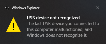
“Did you try unplugging and replugging it? Did you try a different USB port on the computer? Maybe the computer needs a reboot?” None of that fixed it. I stopped by after work to take a look, hoping that it was just some simple glitch that I could resolve.
When I arrived, it quickly became apparent that this was more than a glitch. Whenever I plugged the printer into his computer, a message popped up saying: The last USB device you connected to this computer malfunctioned, and Windows does not recognize it.
For the next post in my series about upgrading my Chumby 8’s Linux kernel (here are links to parts 1, 2, and 3), I thought I’d look at what was involved in getting the reboot and poweroff commands working properly. I noticed pretty early during the development process that they didn’t work, which was pretty annoying.
The system is going down NOW!
Sent SIGTERM to all processes
Sent SIGKILL to all processes
Requesting system reboot
[   46.457580] reboot: Restarting system
[   47.458947] Reboot failed -- System halted
This meant that in order to restart the Chumby, I had to physically press a button to power it off and again to power it back on. As you can imagine, this got old really fast during development. For that reason it was one of the earliest things that I got working.
I actually implemented it in U-Boot first, but I thought the Linux side of it would be more fun to share. If you want to see what was involved on the U-Boot side, see this commit from my fork of U-Boot.